
Oblique-illumination systems and methods

Inactive Publication Date: 2013-07-04
GE HEALTHCARE BIO SCI CORP
View PDF10 Cites 24 Cited by
  • Summary
  • Abstract
  • Description
  • Claims
  • Application Information

AI Technical Summary

Benefits of technology

The patent text is about a system and method for using oblique-illumination in fluorescence microscopy. This system can be attached to a microscope and is used to illuminate an object from any desired direction. The system combines oblique illumination to illuminate the surface of an object and epi-illumination to create fluorescent light from tagged targets. This allows for the capture of images of both the surface features and the targets, which can be used to determine their locations in the sample. The technical effect of this system is improved imaging of surface features and target detection in fluorescence microscopy.

Problems solved by technology

Capturing robust, automated scanned images of fluorescently tagged targets in sample solutions can be challenging.
Without a method or reference point that can be used to determine the three-dimensional location of the tagged cells, it may be difficult to image and perform further analysis on the cells.
However, factors such as manufacturing tolerances, target size, density, and variability in mounting techniques, create uncertainty about the precise location of the target within a region.
However, these techniques have a number of disadvantages.
With fluorescence scanning, the fluorescent signature of the target can be used to search for the target, but the fluorescent signature of the target alone may not be sufficient to determine the location of the target, because signals and contrast due to signal intensity vary from sample to sample, the signal intensity can vary over time, or the background can vary.
Also, extended fluorescence imaging can damage the target making it undesirable to use fluorescence imaging for target finding prior to experimental imaging.
With bright field imaging, expensive optics and a different light path are often required to gain high contrast images.
In some cases, the quality of the fluorescent images may be compromised because a number of the optical components are located in the fluorescent imaging pathway.
With reflection imagining in an epi-fluorescent system, it is often difficult to get the same wavelength from the illumination source to the detector.
Either option may require additional components that add cost and complexity to the system.
This location may not have the high contrast needed for focusing and may not be a useful reference for locating the sample.

Method used


Image

  • Oblique-illumination systems and methods
  • Oblique-illumination systems and methods
  • Oblique-illumination systems and methods

Examples


Embodiment Construction

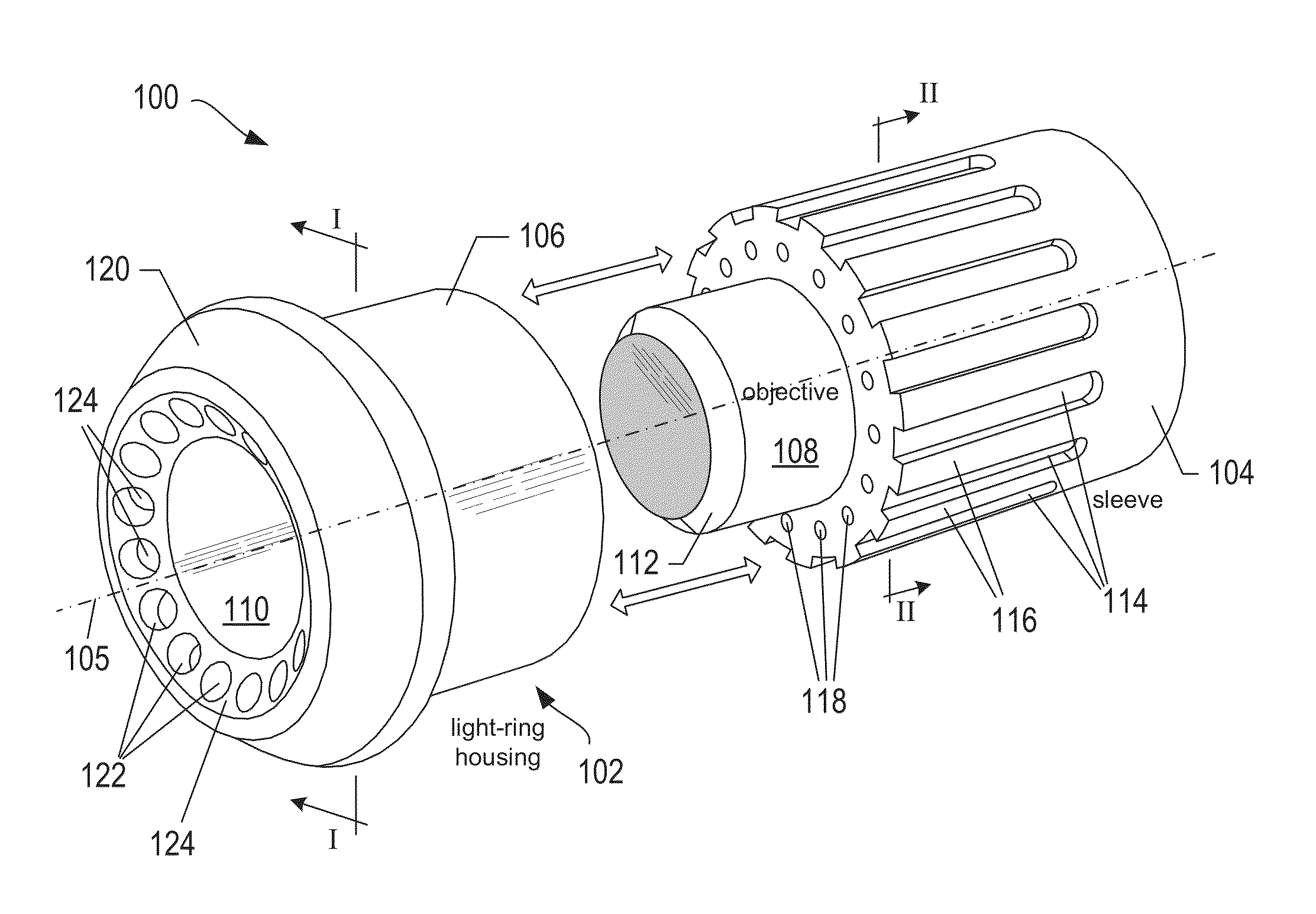
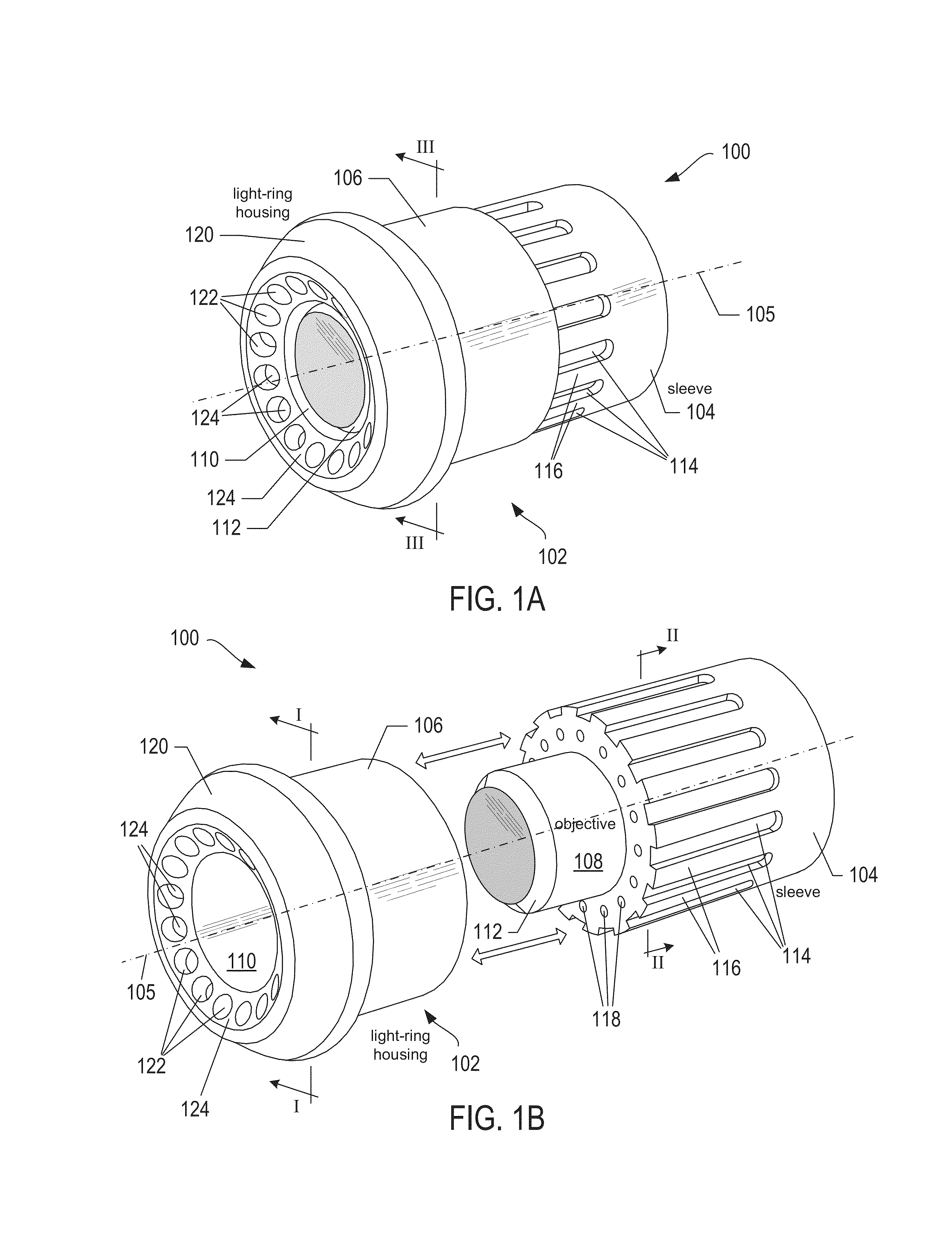
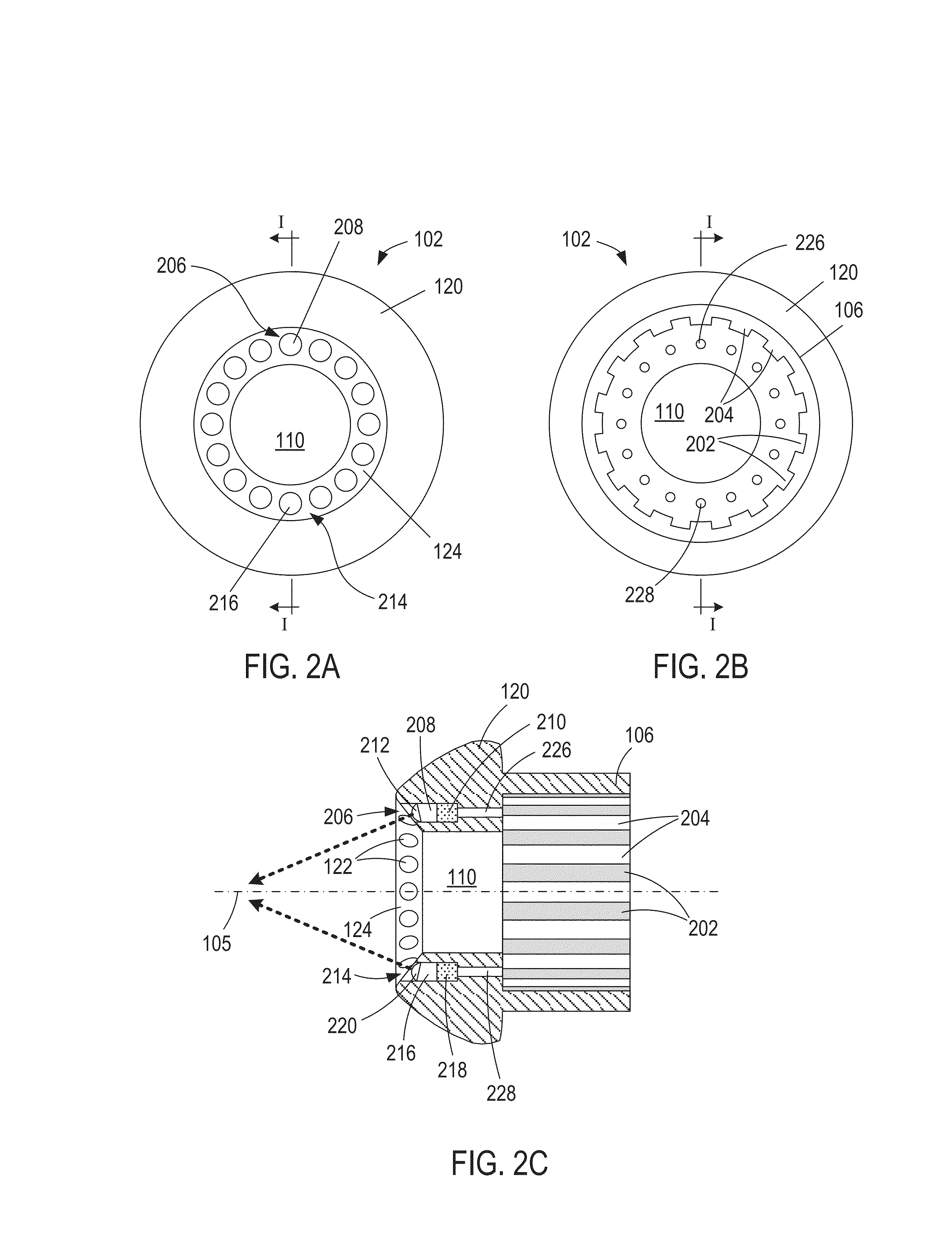
[0024]FIGS. 1A-1B show perspective views of an example oblique-illumination system 100. The system 100 includes a light-ring housing 102 and an objective sleeve 104. The light-ring housing 102 and sleeve 104 are cylindrical and are shown in FIGS. 1A-1B as sharing a common cylindrical axis 105. FIG. 1A shows a perspective view of the sleeve 104 inserted into a cylindrical shell 106 of the housing 102. FIG. 1B shows the sleeve 104 removed from the cylindrical shell 106 and a microscope objective 108 inserted into a cylindrical opening of the sleeve 104 and reveals a cylindrical opening 110 in the housing 102, which is dimensioned to receive the objective 108 so that when then sleeve 104 is inserted into the cylindrical shell 106 of the housing 102, as shown in FIG. 1A, front lens assembly 112 of the objective 108 is exposed. The optical axis of the objective 108 corresponds to the common cylindrical axis 105 of the housing 102 and sleeve 104. FIGS. 1A-1B show a number of radially-spac...


PUM


Abstract

Oblique-illumination systems integrated with fluorescence microscopes and methods of using oblique illumination in fluorescence microscopy are disclosed. An oblique-illumination system is attached to a fluorescence microscope objective. The oblique-illumination system can be used to illuminate from any desired direction the surface of an object located at a fixed known offset away from a sample solution containing fluorescently tagged targets. Oblique illumination is used to illuminate features of the surface while epi-illumination is used to create fluorescent light emitted from the tagged targets. The combination of oblique illumination of the surface and epi-illumination of the targets enables capture of images of the surface features and the fluorescent targets so that the locations of the targets in the sample can be determined based on the locations of the surface features.

Description

CROSS-REFERENCE TO RELATED APPLICATIONS[0001]This application claims priority to U.S. provisional patent application No. 61 / 382,725 filed Sep. 14, 2010, the disclosure of which is incorporated herein by reference in its entirety.TECHNICAL FIELD[0002]This disclosure relates to microscopy, and, in particular, to imaging systems and methods that use oblique-reflection illumination in combination with fluorescence microscopy.BACKGROUND OF THE INVENTION[0003]Capturing robust, automated scanned images of fluorescently tagged targets in sample solutions can be challenging. The images can be used to try to locate the targets for identification, extraction, or isolation. Consider, for example, free-floating fluorescently tagged cells in a sample disposed between a slide and a cover slip. Without a method or reference point that can be used to determine the three-dimensional location of the tagged cells, it may be difficult to image and perform further analysis on the cells.[0004]Conventional...

Claims


Application Information

Patent Timeline
IPC IPC(8): G02B21/06
CPCG02B21/06G02B21/084
Inventor TEPLITZ, KYLABROWN, CARL
Owner GE HEALTHCARE BIO SCI CORP
Learn More