Video encoding method, video decoding method, video encoding apparatus, video decoding apparatus, and programs thereof

a video encoding and video decoding technology, applied in the field of video encoding and video decoding technologies, can solve the problems of limited improvement in coding efficiency and performance, and achieve the effect of reducing overhead, improving locality flexibility, and increasing locality flexibility

Active Publication Date: 2013-07-04
NIPPON TELEGRAPH & TELEPHONE CORP
View PDF11 Cites 13 Cited by
  • Summary
  • Abstract
  • Description
  • Claims
  • Application Information

AI Technical Summary

Benefits of technology

[0046]The present invention can realize division into regions using information on the energy of a residual signal when the division into regions is performed and an interpolation filter is applied to each region, provide a wide variety of types of division into regions, and increase the flexibility in terms of locality in a picture. Moreover, the ranges of divided regions that are divided in accordance with a region classification using encoding information can be adjusted, a wide variety of types of ranges of the regions based on which filters are switched can be provided, and the flexibility in terms of locality in a picture can be improved. Furthermore, a mechanism of reducing overhead is introduced. With the above factors, the present invention can improve the coding efficiency.

Problems solved by technology

Therefore, it is considered that improvement in performance is limited in terms of the coding efficiency.

Method used


Image

  • Video encoding method, video decoding method, video encoding apparatus, video decoding apparatus, and programs thereof
  • Video encoding method, video decoding method, video encoding apparatus, video decoding apparatus, and programs thereof
  • Video encoding method, video decoding method, video encoding apparatus, video decoding apparatus, and programs thereof

Examples


example 1

[Encoding Process (Example 1)]

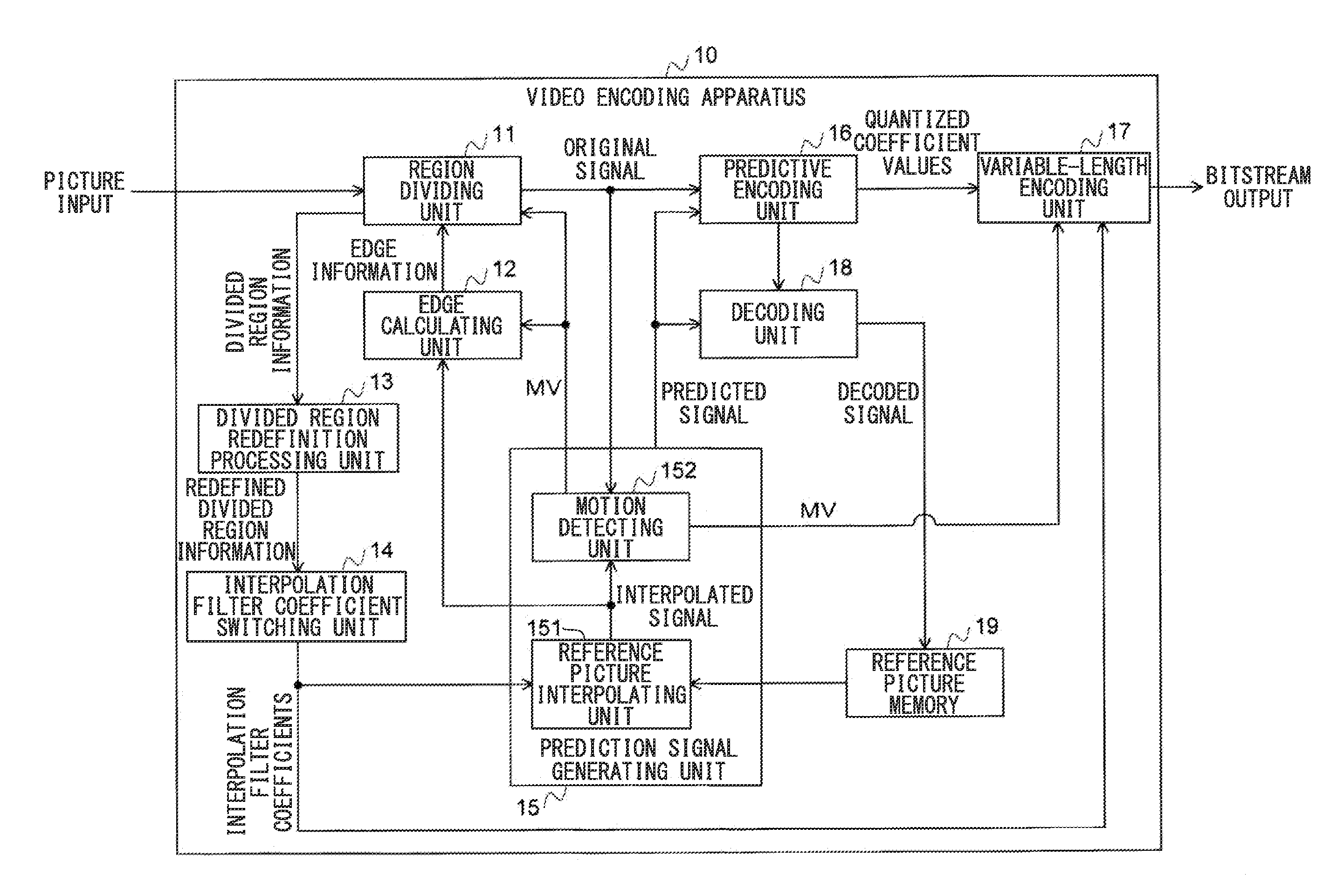
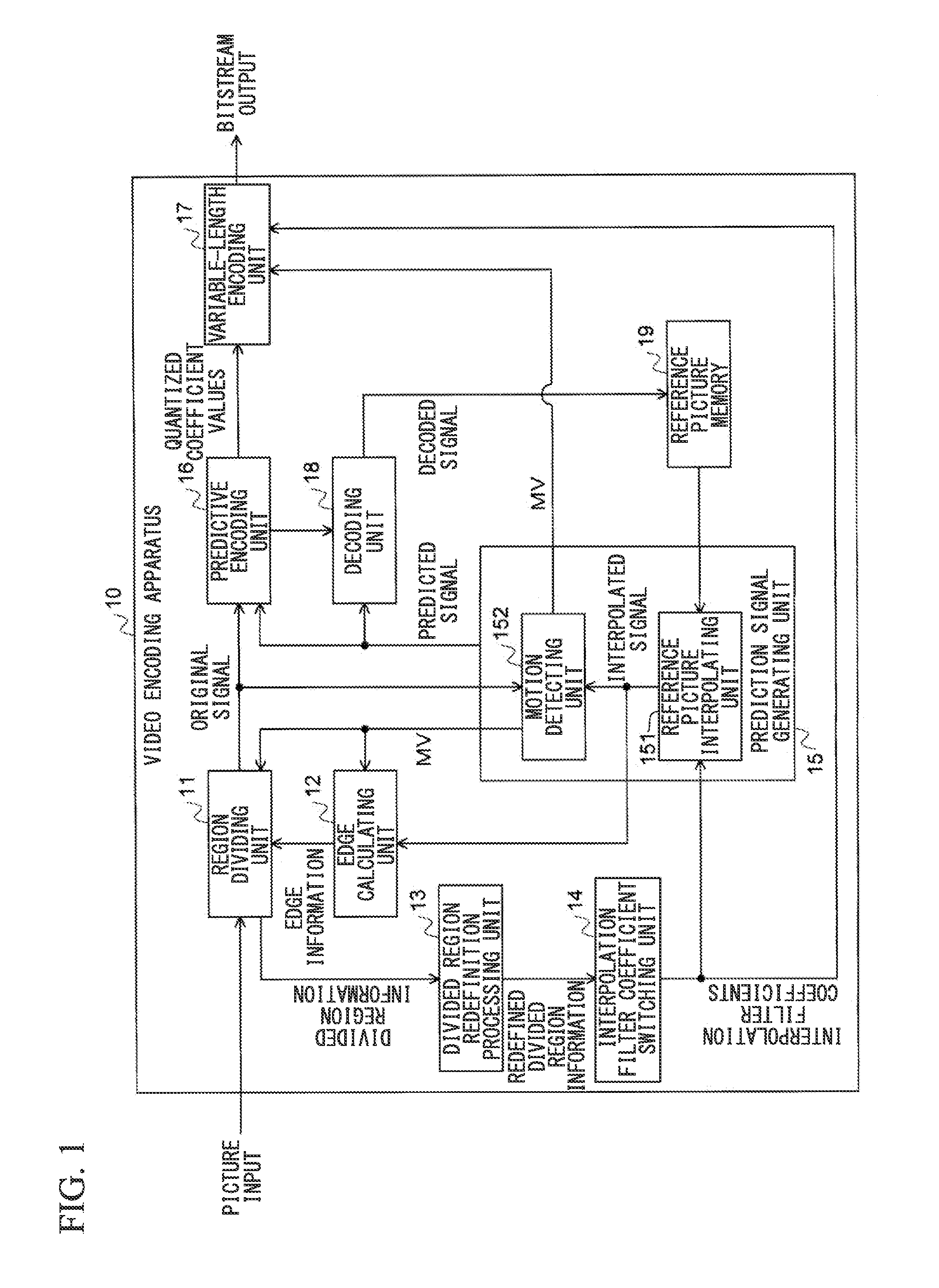
[0075]FIG. 3 is a flowchart of a video encoding process executed by the video encoding apparatus 10. Hereinafter, unless otherwise specified, a description will be given assuming that luminance signals are processed; however, the process can be applied not only to luminance signals but also to chrominance signals. In this example, after division into regions is performed, the ranges of the regions are corrected by a divided region redefinition process, the optimum interpolation filter is derived for each region, and encoding is performed.

[0076]First, in step S101, an encoding target frame is input.

[0077]Subsequently, in step S102, one of predefined division modes is selected. A division mode defines information based on which division (classification) into regions is performed, and all the pieces of encoding information such as a motion vector, spatial coordinates, and texture (edge) information can be used as information for performing the division int...

example 2

[Encoding Process (Example 2)]

[0104]FIG. 9 illustrates a second example of a video encoding process executed by the video encoding apparatus 10. Hereinafter, unless otherwise specified, a description will be given assuming that luminance signals are processed; however, the process can be applied not only to luminance signals but also to chrominance signals. In this example, after division into regions is performed, the ranges of the regions are corrected by a divided region redefinition process, the optimum fixed interpolation filter is determined for each region, and encoding is performed.

[0105]First, in step S201, a frame of an encoding target picture is input.

[0106]Subsequently, in step S202, one of predefined division modes is selected. The division modes have been described in the encoding process (example 1).

[0107]Subsequently, in step S203, the frame is divided into blocks, each block having, for example, a block size of m×n (m and n are positive integers) of motion predictio...

example 3

[Encoding Process (Example 3)]

[0118]FIG. 10 illustrates a third example of a video encoding process executed by the video encoding apparatus 10. Hereinafter, unless otherwise specified, a description will be given assuming that luminance signals are processed; however, the process can be applied not only to luminance signals but also to chrominance signals. In this example, after division into regions is performed, the ranges of the regions are corrected by a divided region redefinition process, the optimum fixed interpolation filter and the optimum filter offset are determined for each region, and encoding is performed.

[0119]First, in step S301, a frame of an encoding target picture is input.

[0120]Subsequently, in step S302, one of predefined division modes is selected.

[0121]Subsequently, in step S303, the frame is divided into blocks, each block having, for example, a block size of m×n (m and n are positive integers) of motion prediction, and the optimum motion vector is calculate...


PUM


Abstract

Regions based on which an interpolation method of a fractional-accuracy pixel is switched are optimized, and the interpolation method is switched for each of the divided regions, thereby reducing residual energy of inter-frame prediction with motion compensation. A video encoding apparatus is provided with: an encoding information acquiring unit which acquires encoding information for each block; a region classification unit which performs a region classification on a block-by-block basis in accordance with the encoding information; a divided region redefinition processing unit which shifts a region dividing line in a horizontal direction, a region dividing line in a vertical direction, or both the region dividing line in the horizontal direction and the region dividing line in the vertical direction based on a result of the region classification, and determines a region dividing line with which density of blocks belonging to a particular region classification is greater than or equal to a predetermined threshold value; an interpolation method switching unit which switches an interpolation method of a fractional-accuracy pixel for each of divided regions divided by the region dividing line; an interpolation performing unit which performs interpolation of the fractional-accuracy pixel for each of the divided regions; a picture encoding unit which encodes a picture using inter-frame prediction with motion compensation of fractional-accuracy for an interpolated picture; and a region classification information encoding unit which encodes information on the region classification.

Description

TECHNICAL FIELD[0001]The present invention relates to video encoding and video decoding technologies that achieve improvement in performance of an interpolation filter in video encoding using inter-frame prediction with motion compensation of fractional-accuracy and improvement in coding efficiency.[0002]Priority is claimed on Japanese Patent Application No. 2010-220560, filed Sep. 30, 2010, the content of which is incorporated herein by reference.BACKGROUND ART[0003]In video encoding, in the case of inter-frame prediction (motion compensation) encoding which performs prediction between different frames, a motion vector is obtained by referring to an already decoded frame so as to minimize the prediction error energy and the like, a residual signal is subjected to orthogonal transform, quantization is applied, and entropy encoding is performed, and binary data is obtained thereby. In order to increase the coding efficiency, it is indispensable to reduce the prediction error energy, ...

Claims


Application Information

Patent Timeline
Patent Type & Authority Applications(United States)
IPC IPC(8): H04N7/26H04N19/50H04N19/102H04N19/117H04N19/134H04N19/139H04N19/14H04N19/147H04N19/154H04N19/196H04N19/463H04N19/523H04N19/553H04N19/59H04N19/593H04N19/70
CPCH04N19/00587H04N19/46H04N19/117H04N19/523H04N19/186H04N19/182H04N19/17H04N19/14H04N19/119H04N19/176H04N19/587
Inventor MATSUO, SHOHEIBANDOH, YUKIHIROTAKAMURA, SEISHIJOZAWA, HIROHISA
Owner NIPPON TELEGRAPH & TELEPHONE CORP
Why Eureka
Try Eureka