Fire resistant optical cable

a technology of optical cables and fiber optic cables, applied in the direction of cables, insulated conductors, instruments, etc., can solve the problems of difficult to achieve high fiber density cables, scarcely effective, and increase the dimensions of final cables, so as to improve the resistance to transversal mechanical stresses and increase the mechanical performance of cables

Active Publication Date: 2013-07-04
PRYSMIAN SPA
View PDF13 Cites 17 Cited by
  • Summary
  • Abstract
  • Description
  • Claims
  • Application Information

AI Technical Summary

Benefits of technology

[0010]Consequently, the Applicant has found that an optical cable can effectively retain its transmission capability during fire occurrence and afterwards when the optical fibers are provided with a tubular layer of a ceramifiable material and when the flame action over such tubular layer is delayed for a time sufficient to allow the ceramifiable material to complete ceramization without collapsing onto the optical fibers.
[0062]dielectric armouring to increase cable mechanical performance according to the specific application;

Problems solved by technology

Initially, the Applicant has noticed that fire resistant optical cables available in the art, although working in many circumstances, require complex and specific constructions including several layers of different materials, which increase not only the manufacturing costs but also the dimensions of the final cable.
Moreover, the necessity of particular core designs makes more difficult to achieve cables with a high fiber density, i.e. a high number of optical fibers per cable section unit.
Moreover, the Applicant has found out that the conventional fire resistant protections are in many circumstances not able to substantially minimize attenuation increase of the optical signal during exposure of the cable to fire, and are also scarcely effective when the fire is extinguished and therefore the cable is no longer heated.
Therefore, the above materials can collapse onto the optical fibers, which, being to a large extent devoid of their polymeric coatings (since (hiring fire they has been mainly burned off), are extremely sensitive to any mechanical stress, which is likely to cause macro- and micro-bending, and thus signal attenuation, and even breakage of the fibers themselves due to local peak loads.

Method used


Image

  • Fire resistant optical cable
  • Fire resistant optical cable
  • Fire resistant optical cable

Examples


example 1

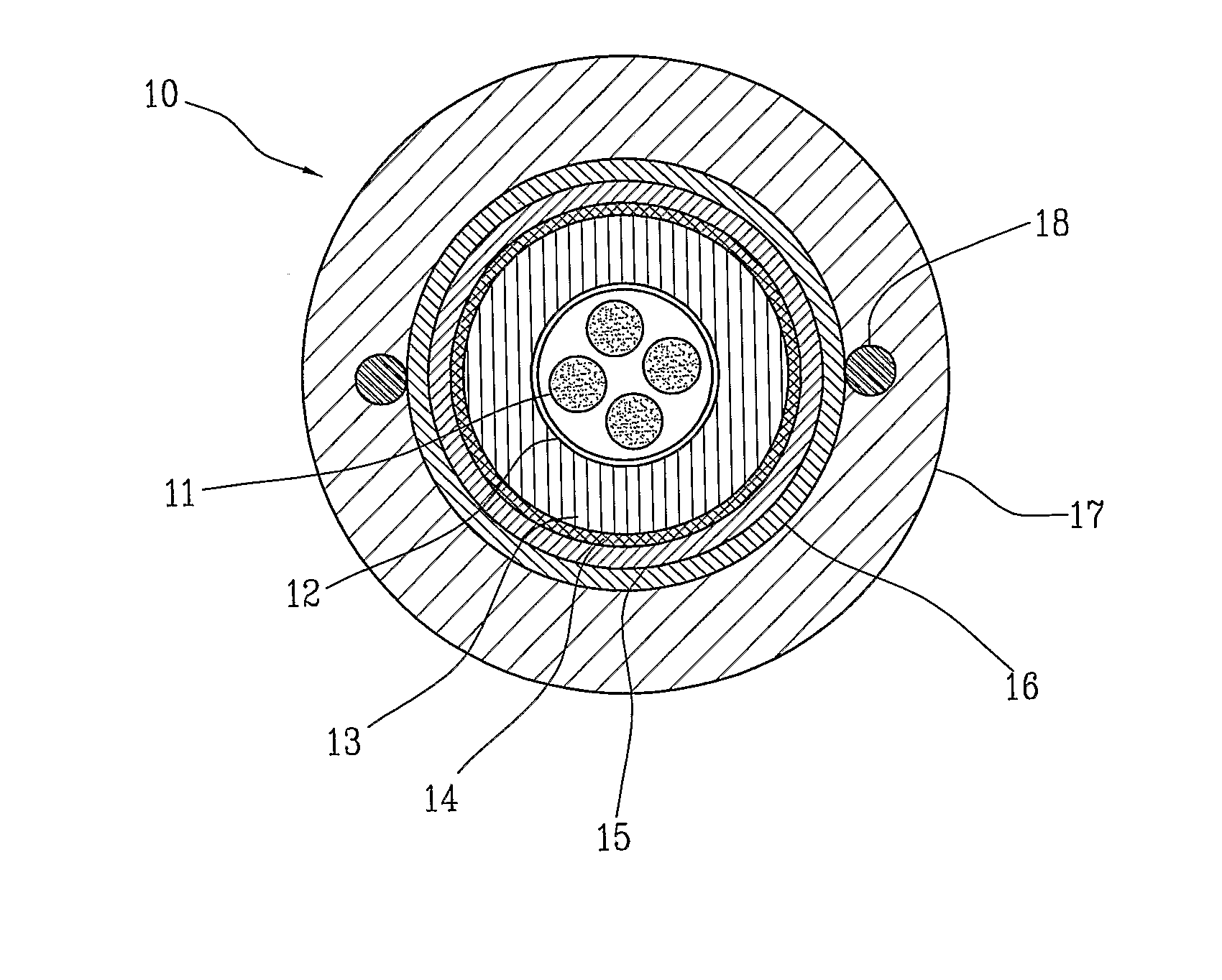
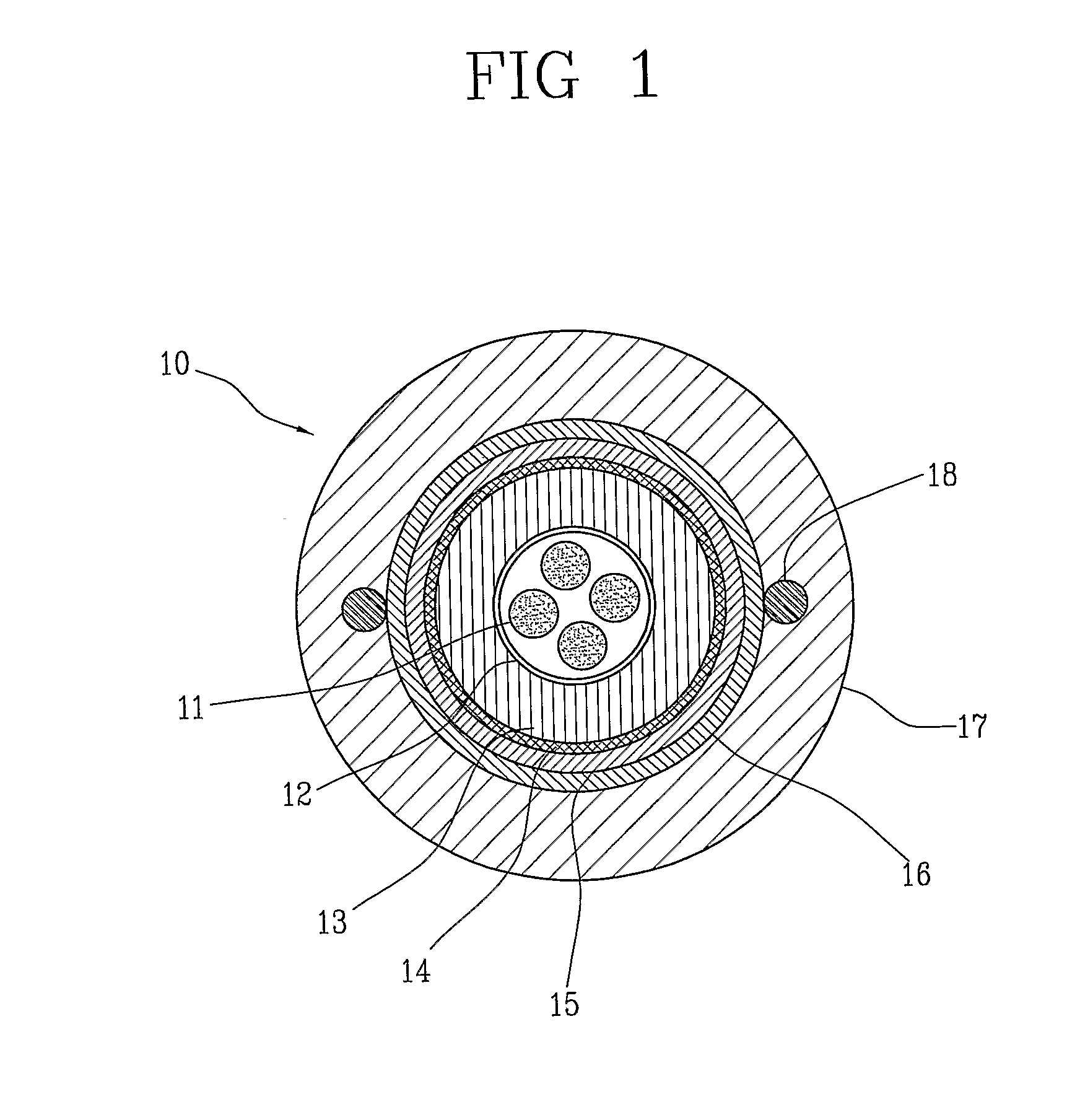
[0083]In a tubular element made from polyethylene, 12 optical fiber micro / nodules were housed. Each micromodule was constituted by 12 optical fibers inserted into a buffer tube of flame retardant polyethylene (Casico FR4805), having an internal nominal diameter of 1.1 mm and an external nominal diameter of 1.4 mm. The buffer tube was filled with a water blocking filler based on silicone gel.

[0084]The tubular element was surrounded by an armour made from a corrugated steel tape longitudinally wrapped and thermally sealed along the overlapping, and then by an outer jacket made from polyethylene, provided with two longitudinal strength members embedded into the outer jacket itself.

[0085]The above optical cable specimen was subject to a test of fire resistance according to international standard TEC 60331-25 (1999, 1st Edition). A cable sample was positioned horizontally by means of two supports and a burner was placed under the sample at a distance of about 75 mm. Propane gas fed the b...

example 2

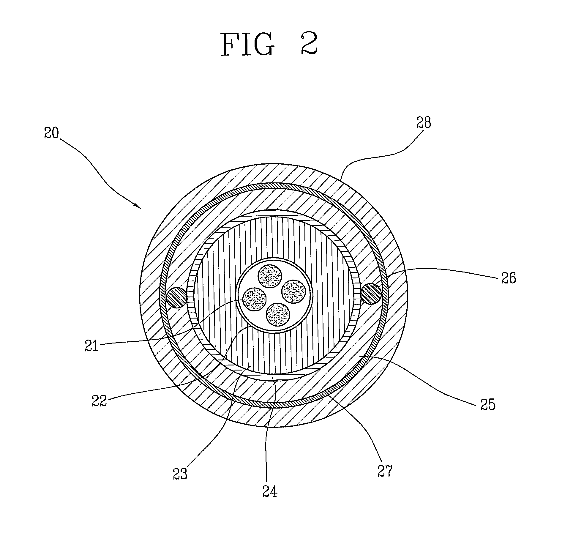
[0088]A cable specimen was produced according to FIG. 1 (but without the all dielectric armour (14) and the water swellable tape (15)), by using 12 optical fiber micromodules as described in Example 1. The flame shielding layer was constituted by the same corrugated steel tape of Example 1. The tubular layer was made from a ceramifiable material having the following composition:

Engage ™ 820023.3% by weightVulkanox ™ HS / LG0.7″Moplen ™ RP 210 G5.8″Whitetex ™23.3″Dynasylan ™ VTMOEO0.1″Glass frit12.7″Nanofxl ™ 55.8″Mistroborid ™ R10 C29.2Engage ™ 8200: ethylenel / 1-oetene copolymer (Dow);Vulkanox ™ HS / LG: 2,2,4-tritnethyl-1,2-dihydroquinoline, polymerized (TMQ antioxidant) (Lanxess);Moplen ™ RP 210 G: propylene homopolymer (Lyondell Basell);Whitetex ™: calcined clay (Engelhard);Dynasylan ™ VTMOEO: vinyltris(2-methoxyethoxy)silane (Degussa);Nanofil  ™ 5: functionalized lamellar nanofiller (Rockwood);Mistrobond  ™ R10 C: talc (Luzenac).

[0089]The final cable had the following characteristic...

example 3

[0092]A cable specimen was produced according to Example 2, but without the corrugated steel tape. During the flame resistance test the ceramifiable layer burned and the optical fibers broke.


PUM


Abstract

A fire resistant optical cable includes: a plurality of optical fibers; at least one tubular layer of a ceramifiable material surrounding the plurality of optical fibers; and at least one flame shielding layer surrounding the tubular layer. The tubular layer of the ceramifiable material is able to mechanically protect the optical fibers not only during heating but also when the fire is extinguished, since it forms a sufficiently robust layer to withstand the mechanical stresses caused by the collapsing of the materials still surrounding the cable, especially in the transition portions between hot and cold zones. The tubular layer of the ceramifiable material is protected by means of at least one flame shielding layer which prevents the flames from directly acting on the ceramifiable material.

Description

BACKGROUND OF THE INVENTION[0001]The present invention relates to a fire resistant optical cable. More particularly, the present invention relates to a fire resistant optical cable which is able to resist to fire and to maintain its optical transmissive properties during and after the fire occurrence for a predetermined period of time.[0002]Optical cables are generally used for medium or long distance telecommunications. There are specific applications where optical cables must have some ability to withstand fire aggression without significantly decreasing their transmission performance. For instance, cables used in fire alarm systems and / or local video surveillance must be able to continue to transmit data / signals in the presence of fire. The functionality of the optical cable must be maintained during the fire occurrence and usually also for a predetermined period of time after the fire is extinguished. Such kind of optical cables are usually installed in galleries and in building...

Claims


Application Information

Patent Timeline
Patent Type & Authority Applications(United States)
IPC IPC(8): G02B6/44
CPCG02B6/4433G02B6/443H01B7/295G02B6/4436
Inventor CONSONNI, ENRICOCAIMI, LUIGICESCHIAT, DAVIDE
Owner PRYSMIAN SPA
Why Eureka
Try Eureka