Power generation apparatus

a power generation apparatus and power technology, applied in mechanical equipment, machines/engines, rotors, etc., can solve the problems of inconvenient maintenance, danger to flying creatures, and inability to meet the needs of urban or suburban residents, and achieve the effect of convenient and inexpensive maintenance and easy operation

Inactive Publication Date: 2013-07-04
BIRKESTRAND ORVILLE J
View PDF7 Cites 10 Cited by
  • Summary
  • Abstract
  • Description
  • Claims
  • Application Information

AI Technical Summary

Benefits of technology

[0005]Accordingly, it is an object of the present invention to provide a wind or water driv

Problems solved by technology

During operation, their relatively rapidly rotating rotor vanes produce annoying sounds and are a danger to flying creatures.
For these and other reasons, conventional wind turbines are not practical or desirable for use in or near urban or suburban neighborhoods where the power is consumed.
On the other hand, water-driven turbines o

Method used


Image

  • Power generation apparatus
  • Power generation apparatus
  • Power generation apparatus

Examples


Embodiment Construction

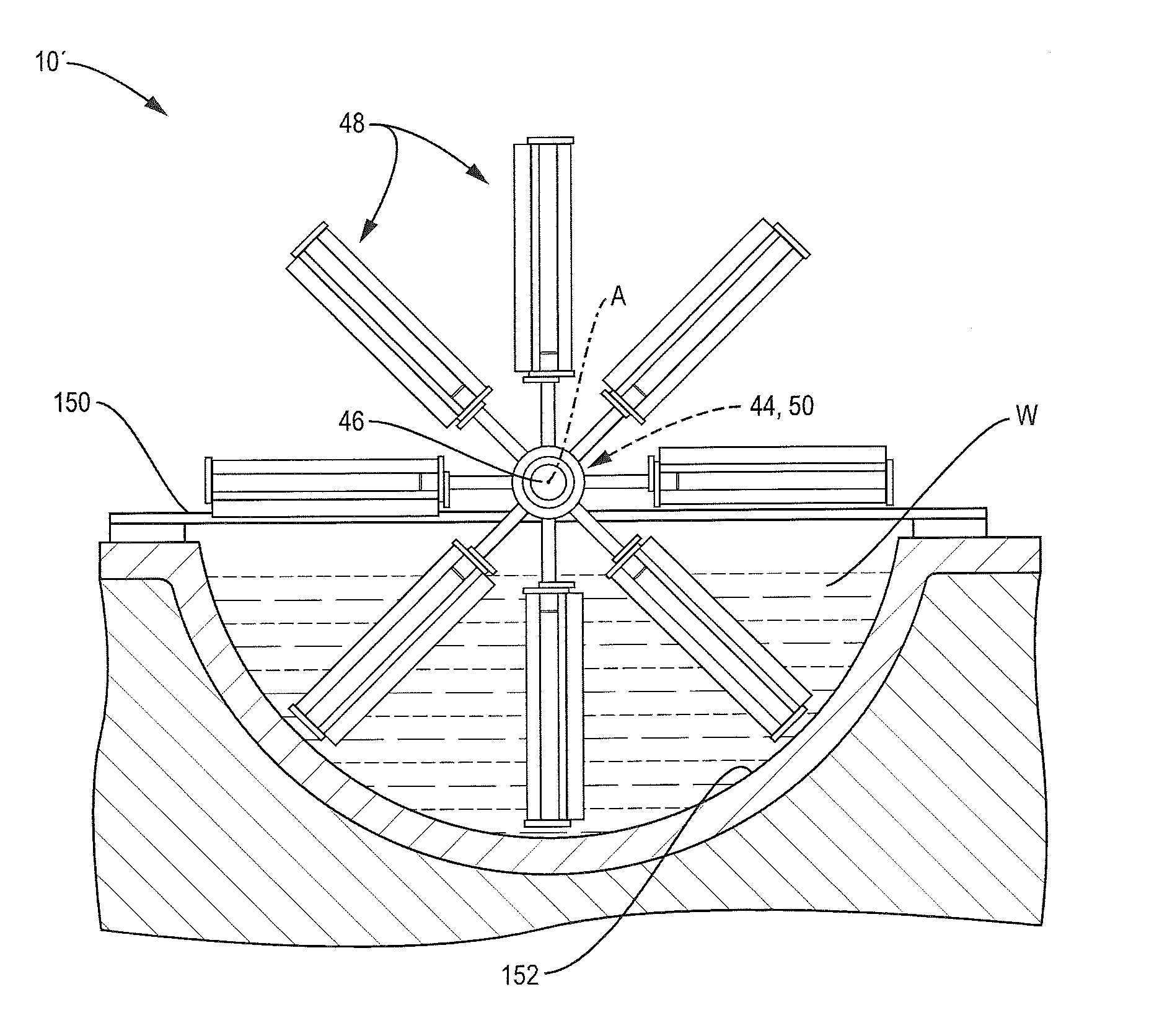
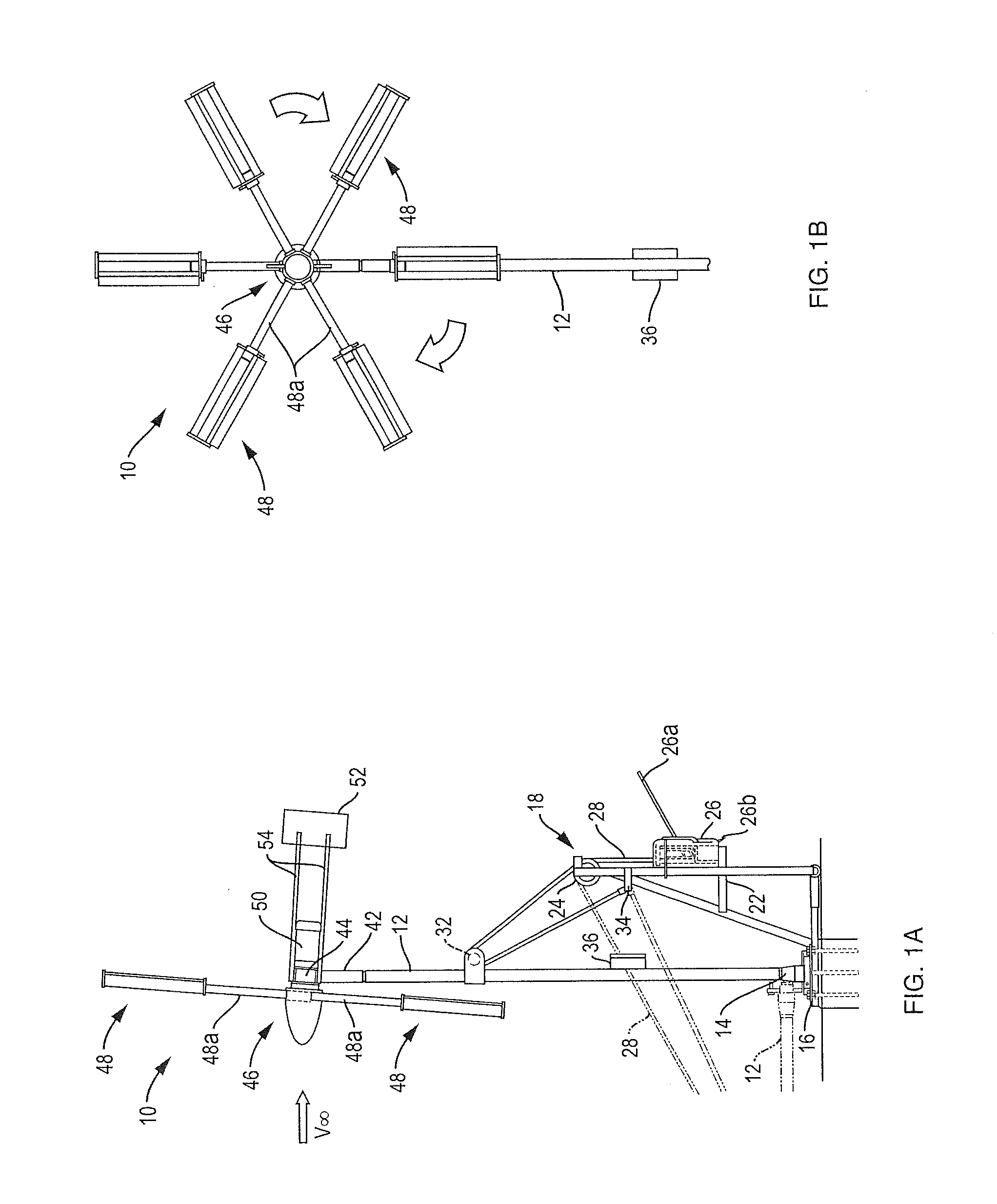
[0029]Referring to FIGS. 1A and 1B of the drawings, a wind powered generating apparatus incorporating the invention is shown generally at 10. The apparatus may be supported at an elevated position by a tower 12 whose lower end is connected by a pivot 14 to a base 16 anchored to the ground. Tower 12 may be moved between a raised position shown in solid lines in FIGS. 1A and 1B and a lower position shown in phantom in FIG. 1A by a removeable hoist mechanism indicated generally at 18 in FIG. 1A. Hoist mechanism 18 includes an upstanding A-frame 22 slideably connected to base 16 between the base and the raised tower pivot 14. A sheave or pulley 24 is pivotally mounted to the apex of A-frame 22 and a continuous cable ratcheting mechanism 26, such as that marketed under the trademark GRIPHOIST® by the Tractel Corp. (www.tractel.com), is mounted to the side of that frame. A cable or wire 28 extending from the top of mechanism 26 passes around sheave 24 and around a second sheave 32 secured...


PUM


Abstract

A power generation apparatus comprises a rotor rotatably mounted to a support and a plurality of vanes extending radially out from the rotor and positioned to be engaged by a moving fluid stream. Each vane includes a wing-shaped main blade having leading and trailing edges, and a co-extensive conditioner blade having leading and trailing edges. The conditioner blade is spaced parallel to the main blade so as to define therebetween a slot having an entrance and an exit. A lift-varying device boarders the slot to vary the lift produced by that vane inversely to the speed of the moving fluid stream so that the rotor turns at a relatively constant rate. The rotor, driven by wind or water, may be coupled to the armature of an induction motor/generator to produce electric power.

Description

CROSS-REFERENCE TO RELATED APPLICATION[0001]This application claims the benefit of Provisional Application No. 61 / 580,731, filed Dec. 28, 2011.BACKGROUND OF THE INVENTION[0002]This application relates to power generation apparatus employing a turbine whose rotor vanes rotate in the presence of a moving wind or water stream to produce an output torque for driving an electric generator to provide grid quality power to a utility grid or to a remote off-grid power system.[0003]Conventional wind turbines are usually large structures mounted atop tall towers. During operation, their relatively rapidly rotating rotor vanes produce annoying sounds and are a danger to flying creatures. For these and other reasons, conventional wind turbines are not practical or desirable for use in or near urban or suburban neighborhoods where the power is consumed. Rather, they are placed in large groups or farms at locations where they can be serviced efficiently and where they are exposed to high velocity...

Claims


Application Information

Patent Timeline
IPC IPC(8): F01D7/00
CPCF01D7/00F03B17/061F03D1/065Y02E10/28Y02E10/721F05B2240/34F03D1/0616F03D1/0633F05B2210/16F05B2240/201F05B2240/31F03B17/062F05B2240/374Y02E10/72Y02E10/30F03D1/0601Y02E10/20
Inventor BIRKESTRAND, ORVILLE J.
Owner BIRKESTRAND ORVILLE J
Why Eureka
Try Eureka