
Drive assembly for use in a robotic control and guidance system

a technology applied in the field of robotic control and guidance system, can solve the problems of complicated use of rcgs to perform mapping functions with certain medical devices (e.g., spiral mapping catheters), and achieve the effect of facilitating the operative engagement of the drive interfa

Active Publication Date: 2013-07-04
ST JUDE MEDICAL ATRIAL FIBRILLATION DIV
View PDF10 Cites 335 Cited by
  • Summary
  • Abstract
  • Description
  • Claims
  • Application Information

AI Technical Summary

Benefits of technology

The invention is a surgical device that has a mechanism for attaching a cartridge to a manipulation base, and a motor that drives the cartridge's components. This design helps to shield the components from contamination and also prevents damage during transportation. When the cartridge is attached to the manipulation base, the motor engages with a special part of the cartridge and causes it to rotate. This allows for the device to be easily operated during surgery.

Problems solved by technology

Arrhythmia can create a variety of dangerous conditions including irregular heart rates, loss of synchronous atrioventricular contractions and stasis of blood flow which can lead to a variety of ailments.
While such systems have proved useful with respect to providing, among other benefits, precise control as described above, the particular use of an RCGS to perform mapping functions with certain medical devices (e.g., spiral mapping catheters) has proved complicated.
This complexity is generally due to the fact that the these medical devices must be rotated into pulmonary veins.
This presents a number of difficulties or issues.
Another issue relating to the use of an RCGS with a rotary or spiral medical device relates to how to shield the medical device and other components disposed in a sterile field (e.g., the table, drapes, the patient, etc.) from contaminants, and therefore, maintain sterility, when a non-sterile manipulating system is used.

Method used


Image

  • Drive assembly for use in a robotic control and guidance system
  • Drive assembly for use in a robotic control and guidance system
  • Drive assembly for use in a robotic control and guidance system

Examples


Embodiment Construction

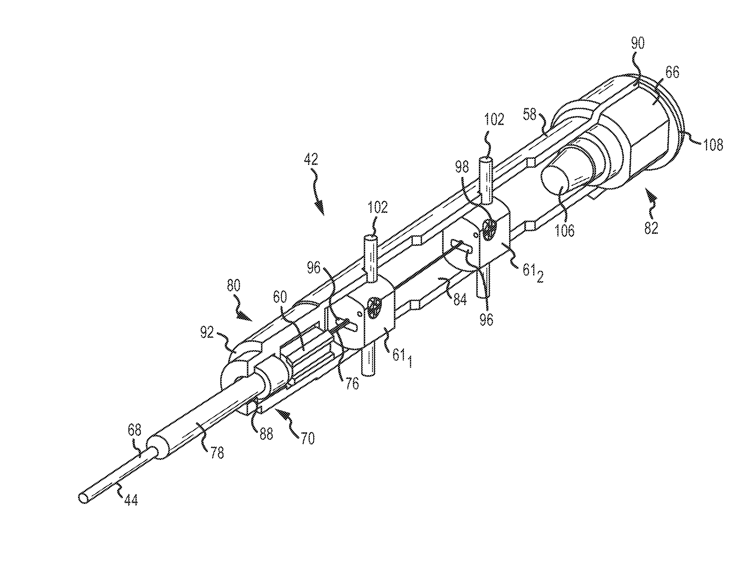
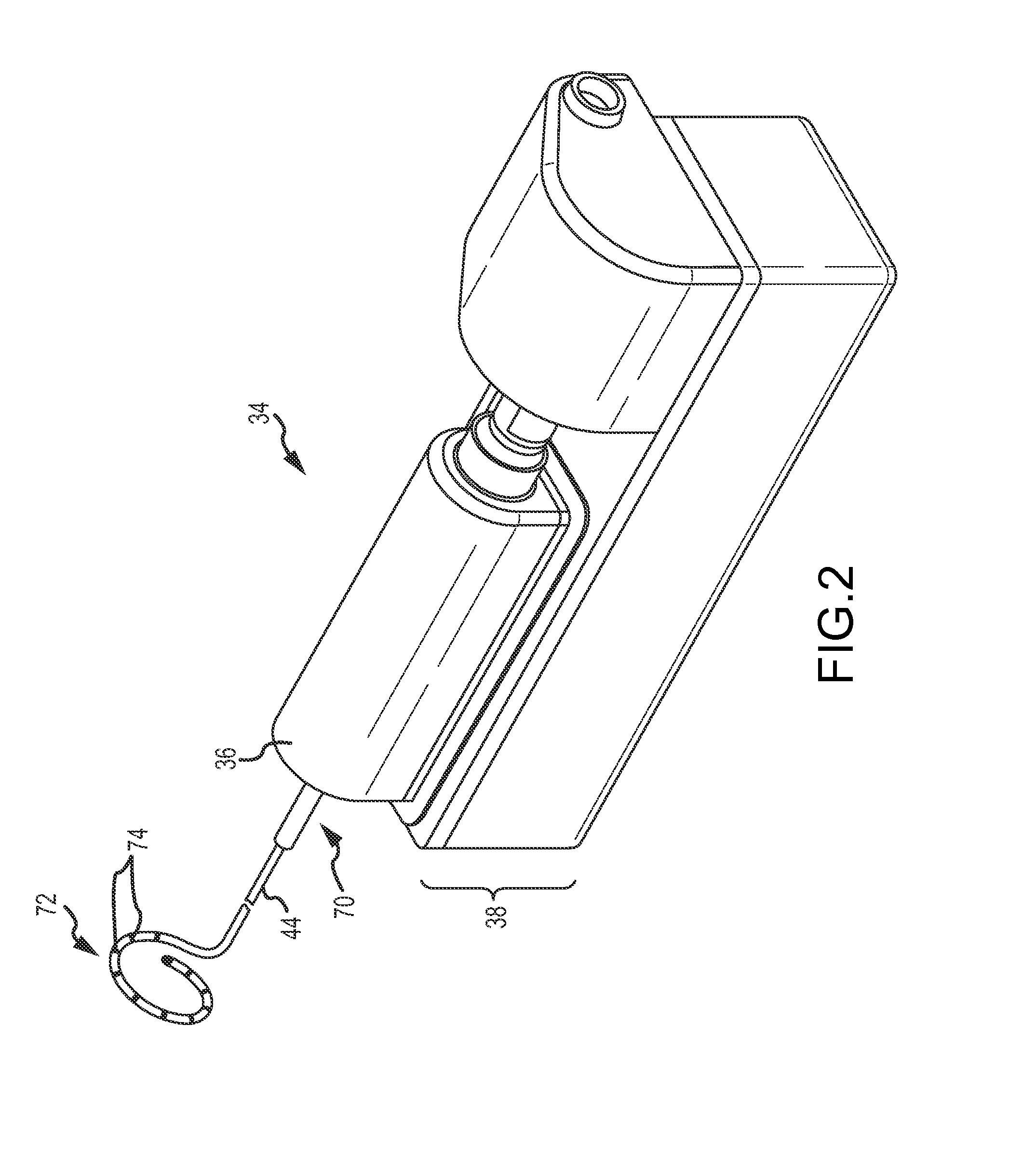
[0045]Before proceeding to a detailed description of a drive assembly for use in a robotically controlled guidance system (RCGS), a brief overview (for context) of an exemplary RCGS for manipulating one or more medical devices will first be provided. The description of the RCGS will, in general terms, detail the various components of an exemplary RCGS. Following that description, the present specification will describe the drive assembly for use in an RCGS.

[0046]Exemplary RCGS System Description.

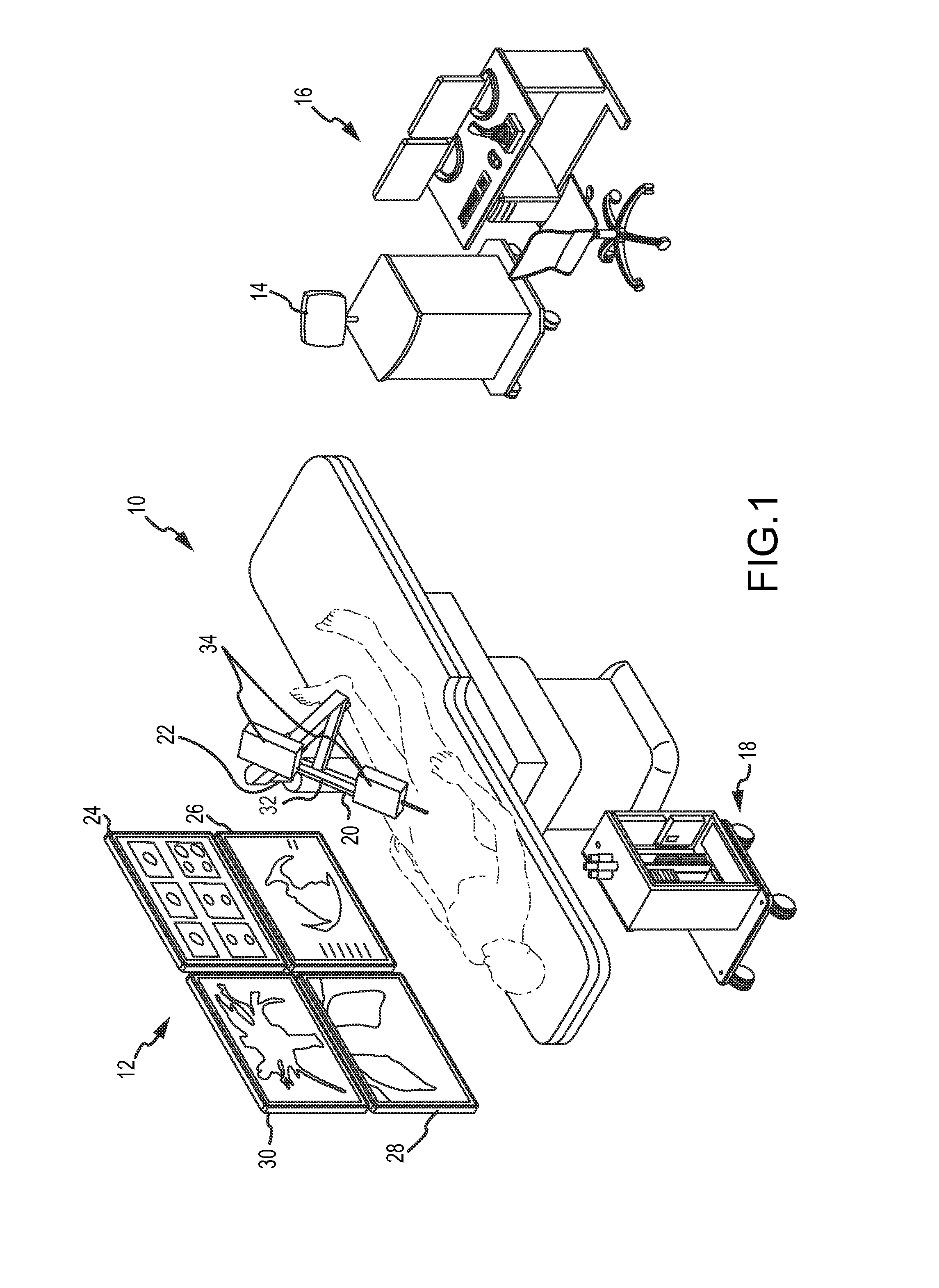
[0047]Referring now to the drawings wherein like reference numerals are used to identify identical components in the various views, FIG. 1 illustrates one exemplary embodiment of a robotic control and guidance system 10 (RCGS 10) for manipulating one or more medical devices. The RCGS 10 can be used, for example, to manipulate the location and orientation of catheters, such as, for example, mapping catheters, and sheaths in a heart chamber or in another body cavity or lumen. The RCGS 10 thus ...


PUM


Abstract

A drive assembly for use in a robotic control and guidance system comprises a cartridge having an outer housing and a rotatable medical device assembly disposed therein. The rotatable assembly includes a medical device having proximal and distal ends, and a housing having first and second ends, and a longitudinal axis extending therethrough. The proximal end of the medical device is disposed within the housing, and the housing further comprises an opening through which the medical device extends outwardly from said housing. The rotatable assembly further comprises a drive interface coupled with the housing. The drive assembly further comprises a manipulation base comprising a mounting plate onto which the cartridge is removably attached, and a drive system mounted to the mounting plate. The drive system is configured to operatively engage the cartridge drive interface and to impart rotational movement onto the rotatable assembly through the drive interface.

Description

BACKGROUND OF THE INVENTION[0001]a. Field of the Invention[0002]The present disclosure relates generally to a robotic control and guidance system (RCGS) for one or more medical devices. More particularly, the present disclosure relates to a drive assembly for use in a RCGS that comprises, for example, a manipulation base and a medical device cartridge for a medical device, such as, for example, a spiral mapping catheter.[0003]b. Background Art[0004]Electrophysiology (EP) catheters are used in a variety of diagnostic and / or therapeutic medical procedures to correct conditions such as atrial arrhythmia, including for example, ectopic atrial tachycardia, atrial fibrillation, and atrial flutter. Arrhythmia can create a variety of dangerous conditions including irregular heart rates, loss of synchronous atrioventricular contractions and stasis of blood flow which can lead to a variety of ailments.[0005]In a typical EP procedure, a physician manipulates a catheter through a patient's vasc...

Claims


Application Information

Patent Timeline
IPC IPC(8): A61B5/04A61M25/092
CPCA61B5/042A61B19/2203A61M25/0113A61B2019/464A61B2019/2211A61B2090/064A61B2034/301A61B34/30A61B5/283
Inventor KIRSCHENMAN, MARK B.
Owner ST JUDE MEDICAL ATRIAL FIBRILLATION DIV
Learn More