Surface plasmon resonance fluorescence analysis device and surface plasmon resonance fluorescence analysis method

a surface plasmon and fluorescence analysis technology, applied in fluorescence/phosphorescence, luminescent dosimeters, optical radiation measurement, etc., can solve the problems of lowering the precision of measuring light resulting from enhanced electric field, excitation optical system likely to vibrate, reflection position likely to displace, etc., to suppress the lowering of the s/n ratio of a signal, suppress the effect of displacemen

Active Publication Date: 2013-07-11
OTSUKA PHARM CO LTD
View PDF0 Cites 23 Cited by
  • Summary
  • Abstract
  • Description
  • Claims
  • Application Information

AI Technical Summary

Benefits of technology

[0011]In view of the above, an object of the invention is to provide, in an analysis device utilizing SPFS, a surface plasmon resonance fluorescence analysis device and a surface plasmon resonance fluorescence analysis method that enable to suppress displacement of the reflection position of excitation light on a metal film, while suppressing lowering of the S / N ratio of a signal to be obtained by measuring light resulting from an enhanced electric field that is generated near the metal film on a prism.

Problems solved by technology

As a result of the above operation, the reflection position (irradiation position) of excitation light on the reflection film is likely to displace, resulting from slight displacement of the incident angle of the excitation light with respect to the metal film.
Since the region of electric field enhanced by surface plasmon resonance is narrow, such displacement of the reflection position of excitation light may result in lowering the precision in measuring light resulting from the enhanced electric field.
However, in the former apparatus, since the entirety of the excitation optical system provided with a light source and lenses is made to swing by a link mechanism, the excitation optical system is likely to vibrate due to the weight thereof.
Further, since the link mechanism is constituted of many components, the reflection position of excitation light on a metal film may displace, resulting from backlash of each of the components.

Method used


Image

  • Surface plasmon resonance fluorescence analysis device and surface plasmon resonance fluorescence analysis method
  • Surface plasmon resonance fluorescence analysis device and surface plasmon resonance fluorescence analysis method
  • Surface plasmon resonance fluorescence analysis device and surface plasmon resonance fluorescence analysis method

Examples


Embodiment Construction

[0025]In the following, an embodiment of the invention is described referring to the accompanying drawings.

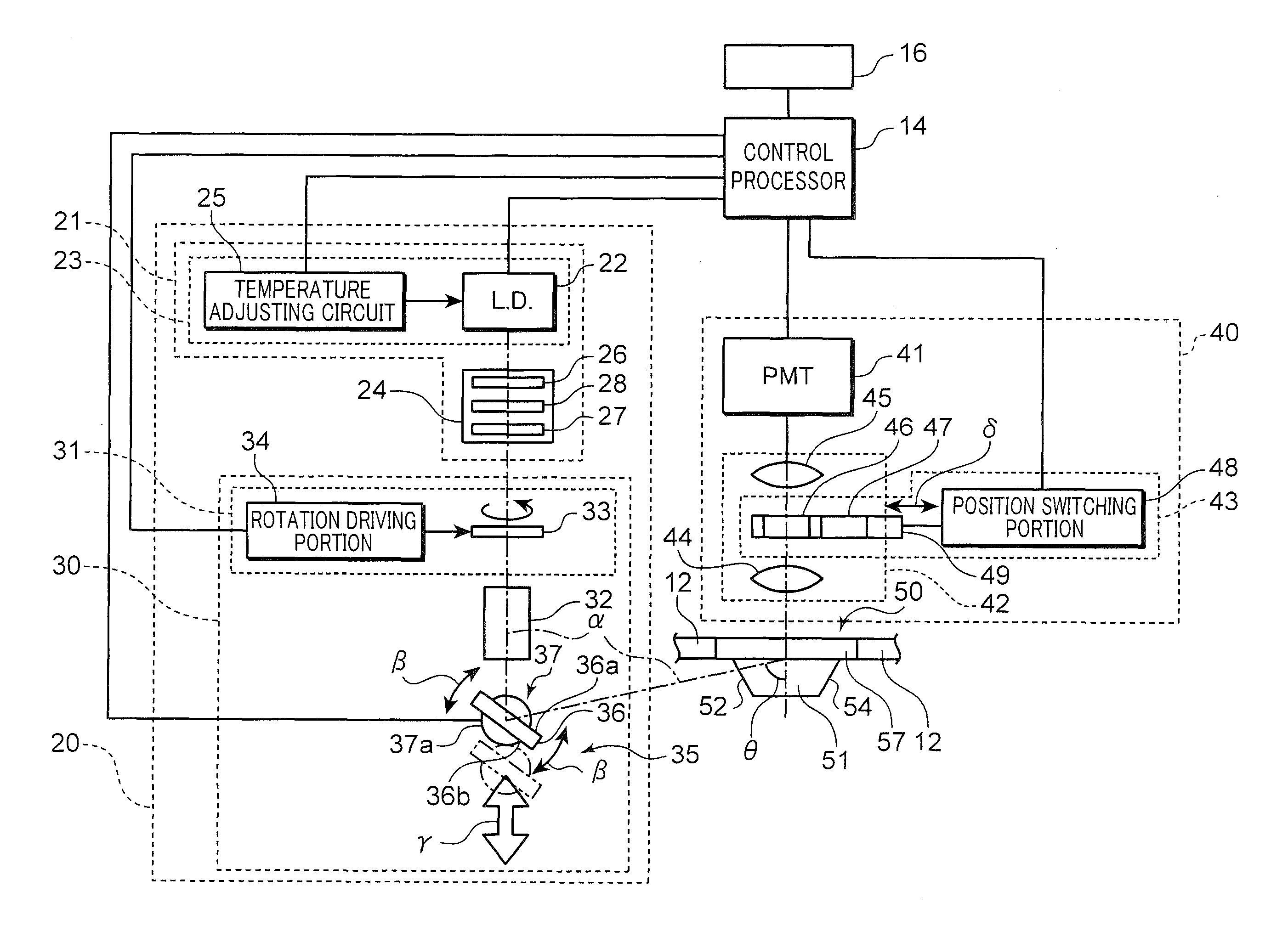
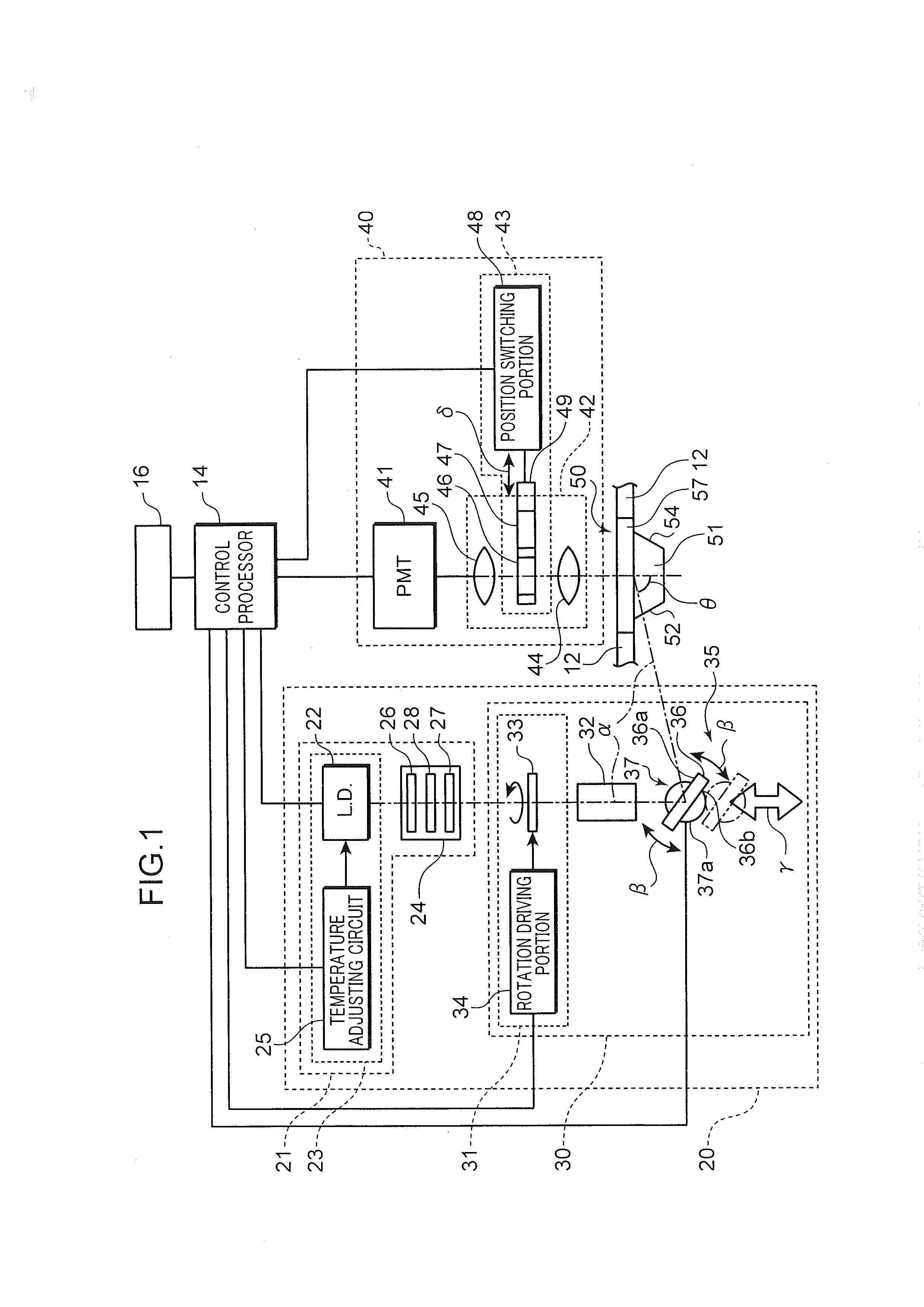
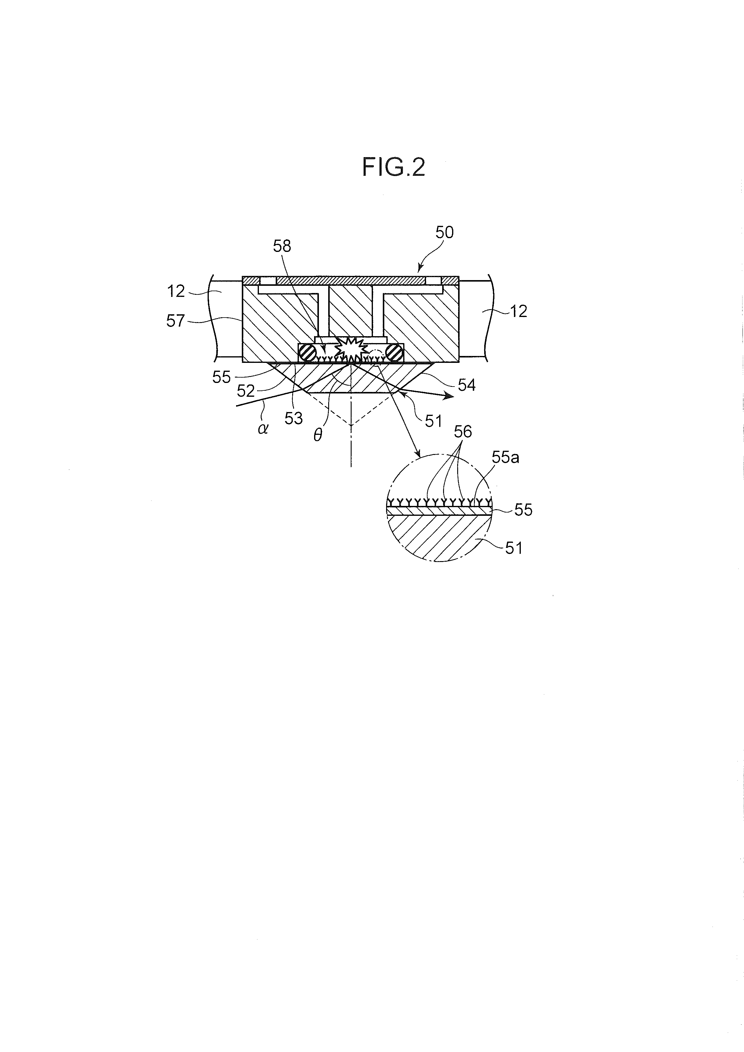
[0026]A surface plasmon resonance fluorescence analysis device (hereinafter, also simply called an “analysis device”) according to the embodiment is configured to excite a fluorescent material labeled on a material to be detected (hereinafter, also simply called a “specimen”), utilizing an evanescent wave (enhanced electric field) emerging from a reflection interface of a prism, in the case where excitation light entered to the prism is reflected on the reflection interface, while undergoing total reflection on the reflection interface. The analysis device is configured to detect the specimen by detecting the light amount of fluorescence generated by excitation of the fluorescent material.

[0027]As shown in FIG. 1, the analysis device is provided with a chip holding portion 12 for holding an analysis chip 50; an excitation light emitting portion 20 for outputting excitation ligh...


PUM

PropertyMeasurementUnit
refractive indexaaaaaaaaaa
incident angleaaaaaaaaaa
surface plasmon resonance fluorescence analysisaaaaaaaaaa

Abstract

In the present invention, a specimen is made to flow on a metal film on a prism, and excitation light (α) is emitted in a predetermined direction. By changing the position of a reflective member that reflects the excitation light (α), and adjusting the orientation of a reflective surface of the reflective member, the incident angle (θ) is changed while maintaining a state in which the excitation light (α) that enters the prism is reflected at a specific position on the metal film. The intensity of light to be generated on the metal film is measured, and the reflective member is positioned to match the position of the reflective member and the orientation of the reflective surface when a maximum amount of light is measured.

Description

TECHNICAL FIELD[0001]The present invention relates to a surface plasmon resonance fluorescence analysis device and a surface plasmon resonance fluorescence analysis method configured to detect a specimen contained in a sample solution, utilizing surface plasmon resonance (SPR).BACKGROUND ART[0002]Conventionally, in biomeasurement for detecting proteins or DNAs, there has been known a surface plasmon resonance fluorescence analysis method (Surface Plasmon-field enhanced Fluorescence Spectroscopy: SPFS), as a method for detecting a specimen (material to be detected) with high sensitivity.[0003]According to SPFS, a prism having a metal film made of e.g. gold or silver formed on a predetermined surface thereof is prepared, excitation light is caused to enter the metal film from the side of the prism in such a manner that the predetermined surface is subjected to total reflection, and light (evanescent wave) emerging from the metal film in reflecting the excitation light on the metal fil...

Claims


Application Information

Patent Timeline
Patent Type & Authority Applications(United States)
IPC IPC(8): G01N21/64
CPCG01N21/64G01N21/648G01N21/553
Inventor WADA, SHIGERU
Owner OTSUKA PHARM CO LTD
Why Eureka
Try Eureka