Automated Dewpoint Oxygen Measurement System

a measurement system and oxygen technology, applied in the direction of instruments, heat treatment equipment, investigating phase/state change, etc., can solve the problems of parts scrapping or remachining, parts that are scrapped or remachined, and parts that are not working properly

Active Publication Date: 2013-07-11
PRATT & WHITNEY +1
View PDF4 Cites 2 Cited by
  • Summary
  • Abstract
  • Description
  • Claims
  • Application Information

AI Technical Summary

Problems solved by technology

Any deviation away from those standards or thresholds can result in malfunctioning components.
If those components are used, the overall machine in which they are employed may under-perform.
If they are not sufficient, the parts are either scrapped or remachined.
Either way, the result is added cost and lessened efficiency.
One example where this is currently problematic is in the manufacture of turbines and other components used in gas turbine engines and other aircraft components.
If they are not adhered to, it may cause deficiencies in the processed parts as well as damage to the measuring equipment.
Not only is this manual verification labor intensive, but prone to human error.
For example, the repetition of the task throughout the day may lead to tedium and mistakes.
Moreover, the manual purging and verification process occupies the operator, often precluding him or her from performing any other task, thus slowing production.

Method used


Image

  • Automated Dewpoint Oxygen Measurement System
  • Automated Dewpoint Oxygen Measurement System
  • Automated Dewpoint Oxygen Measurement System

Examples


Embodiment Construction

[0013]The disclosure and various features and advantageous details thereof are explained more fully with reference to the non-limiting embodiments that are illustrated in the accompanying drawings and detailed in the following description. It should be noted that the features illustrated in the drawings are not necessarily drawn to scale. Descriptions of well-known components and processing techniques are omitted so as to not unnecessarily obscure the embodiments of the disclosure. The examples used herein are intended merely to facilitate an understanding of ways in which the embodiments of the disclosure may be practiced and to further enable those of skill in the art to practice the embodiments of the disclosure. Accordingly, the examples should not be construed as limiting the scope of the disclosure.

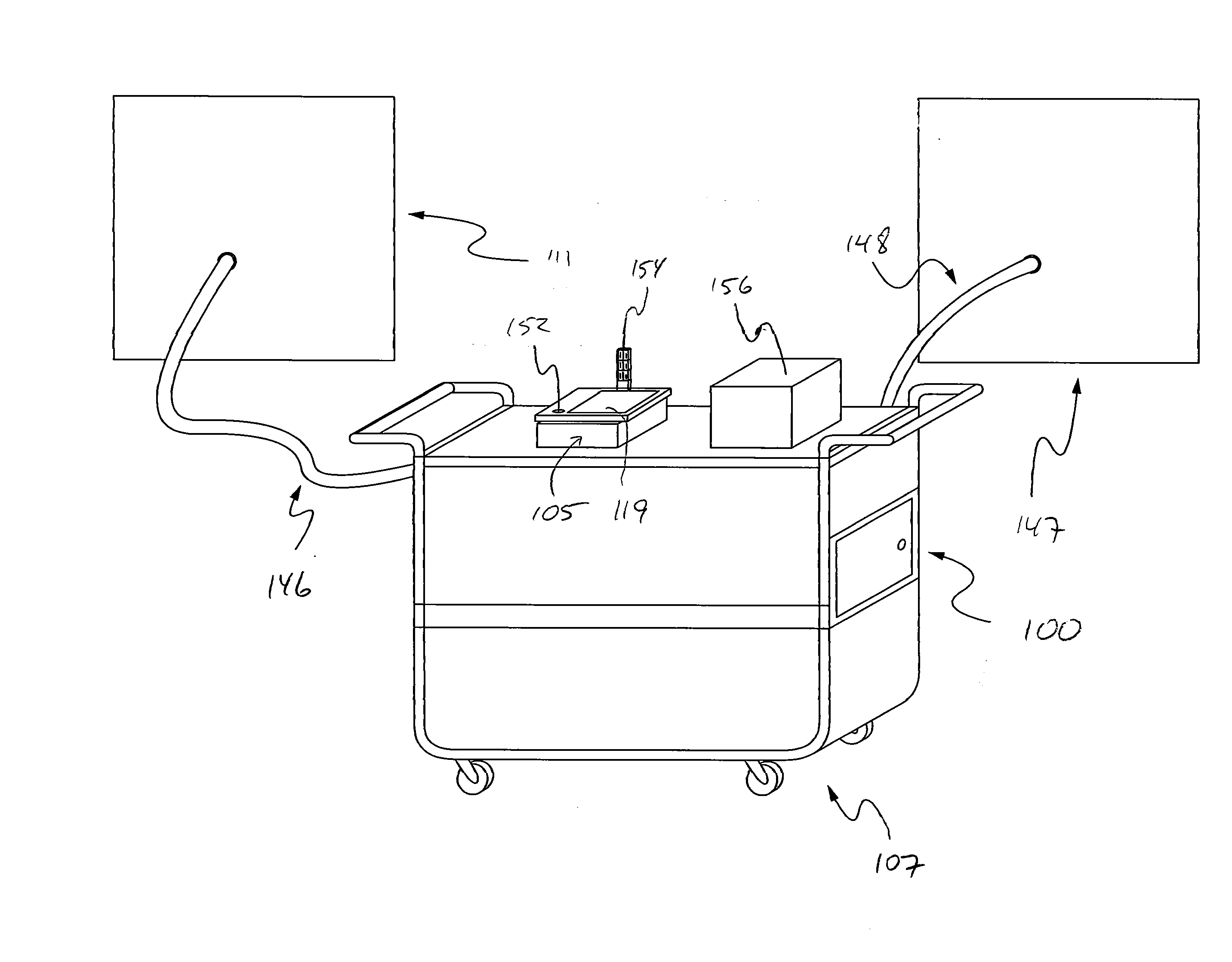
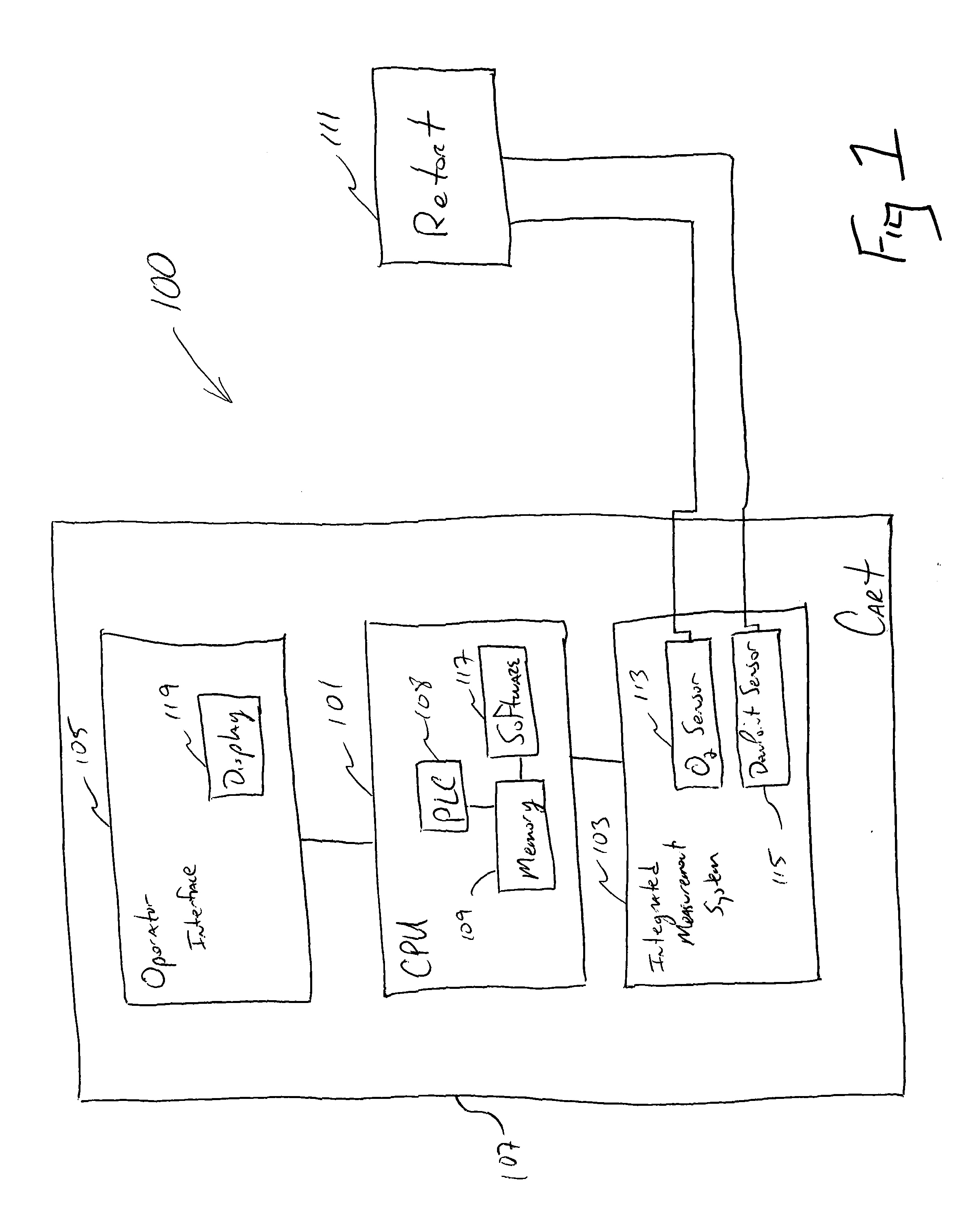
[0014]Referring now to the drawings, and with specific reference to FIG. 1, a block diagram of the automated measurement and verification system 100 according to some embodiments of...


PUM

PropertyMeasurementUnit
current statusaaaaaaaaaa
treatment timeaaaaaaaaaa
massaaaaaaaaaa

Abstract

An apparatus and method to automate the process of measuring and verifying trace gas levels such as oxygen and dewpoint inside a retort used to coat or heat treat substrates are provided. The apparatus may include an integrated measuring system, and an operator interface. The method may include coupling the apparatus to the retort in which the substrate is coated or heat treated, activating the integrated measuring system to measure and verify atmospheric conditions within the retort, and providing operator access to process parameters and status through the operator interface. The measurement and verification system may be completely autonomous.

Description

FIELD OF THE DISCLOSURE[0001]The present disclosure generally relates to systems and methods for coating or heat treating a substrate, and in particular to automated measurement and verification systems for assuring a retort used for such operations meets suitable dewpoint and oxygen levels prior to engaging in same.BACKGROUND OF THE DISCLOSURE[0002]In manufacturing many industrial parts, coatings of a particular material to the parts need to be applied to exacting standards. In others, heat treatments of the parts has to be undertaken to precise standards as well. Any deviation away from those standards or thresholds can result in malfunctioning components. If those components are used, the overall machine in which they are employed may under-perform. Accordingly, they are often rigorously tested prior to installation. If they are not sufficient, the parts are either scrapped or remachined. Either way, the result is added cost and lessened efficiency.[0003]One example where this is...

Claims


Application Information

Patent Timeline
Patent Type & Authority Applications(United States)
IPC IPC(8): G01N25/02
CPCC21D11/00C21D1/74
Inventor VERCH, JR., MANFRIED CARLHORNIAK, PETER N.
Owner PRATT & WHITNEY
Why Eureka
Try Eureka