Optical communication system, and transmitter and receiver apparatus therefor

a communication system and optical communication technology, applied in the field of optical communication systems, can solve the problems of complex receivers, increased frequency bandwidth, and increased frequency bandwidth, and achieve the effect of reducing the number of receivers

Inactive Publication Date: 2013-07-11
EMCORE INC
View PDF36 Cites 23 Cited by
  • Summary
  • Abstract
  • Description
  • Claims
  • Application Information

AI Technical Summary

Benefits of technology

[0008]Another aspect of the invention provides for a receiver having a wavelength-dependent beam splitter arrangement for splitting a received optical signal into two portions which are each directed to respective detectors. A first spectral component at a first frequency is preferentially split into the first portion, and a second spec

Problems solved by technology

One problem with increasing data rates is the consequent increase in frequency bandwidth, which is problematic due to increased dispersion in optical fibers and also because an increase in frequency bandwidth requires a greater frequency spacing of data

Method used


Image

  • Optical communication system, and transmitter and receiver apparatus therefor
  • Optical communication system, and transmitter and receiver apparatus therefor
  • Optical communication system, and transmitter and receiver apparatus therefor

Examples


Embodiment Construction

[0019]Details of the present invention will now be described, including exemplary aspects and embodiments thereof. Referring to the drawings and the following description, like reference numbers are used to identify like or functionally similar elements, and are intended to illustrate major features of exemplary embodiments in a highly simplified diagrammatic manner. Moreover, the drawings are not intended to depict every feature of actual embodiments nor the relative dimensions of the depicted elements, and are not drawn to scale.

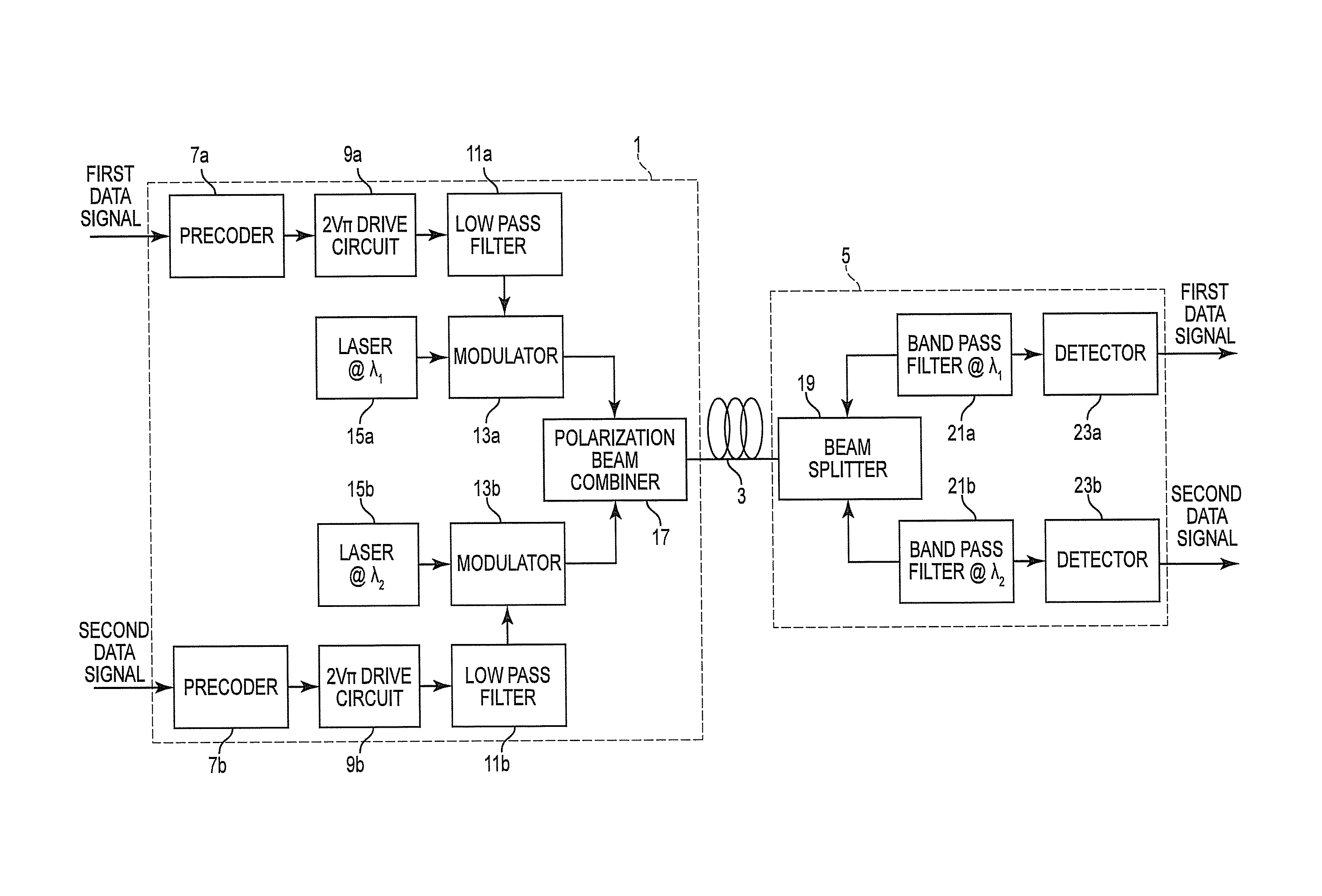
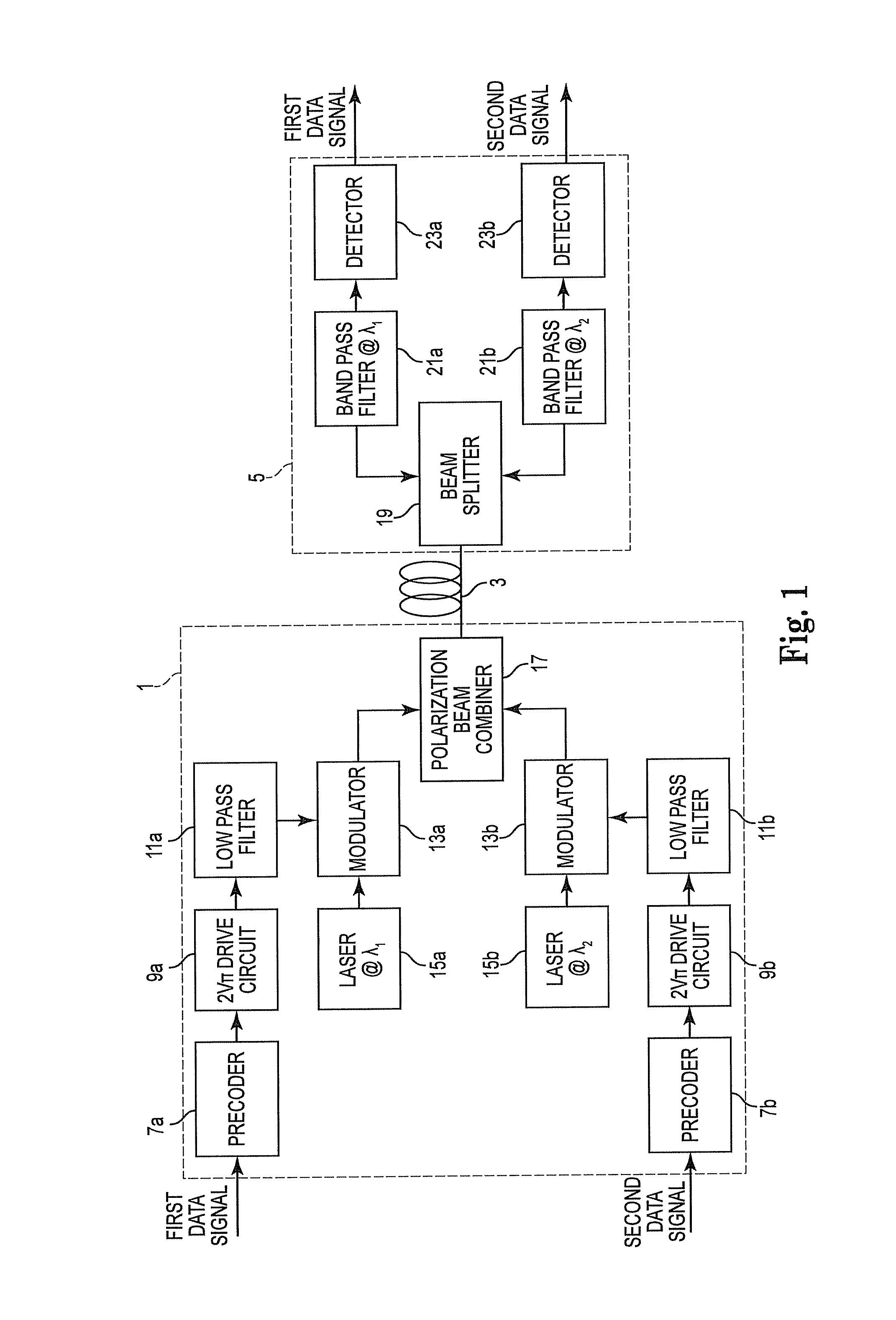
[0020]As shown in FIG. 1, in an optical communication system according to the present invention a transmitter 1 transmits a modulated optical signal through an optical fiber 3 to a receiver 5. The optical signal is modulated in accordance with first and second data signals which are input to respective precoders 7a, 7b of the transmitter 1. In this embodiment, each data signal conveys data serially at a data rate of 22 Gigabits per second (Gbps). The pair ...


PUM


Abstract

An optical communication system having a transmitter in which a pair of optical signals having different frequencies are modulated using a duobinary encoding scheme, and then multiplexed using polarization division multiplexing. Advantageously, the frequency difference between the two signals can be less than the data rate conveyed by each signal, resulting in a narrow spectral bandwidth, while still allowing demultiplexing at a receiver using simple bandpass filters and without the need of any form of polarization tracking. A receiver has a beam splitter for splitting the received optical signal into two portions which are each directed, via respective bandpass filters centred at slightly different frequencies, to respective detectors. Advantageously, the frequency difference between the frequencies at which the bandpass filters are centred can be less than the data rate of a detected signal. The receiver does not require any polarization tracking or balancing, and accordingly is straightforward to implement

Description

BACKGROUND OF THE INVENTION[0001]1. Field of the Invention[0002]The present invention relates to an optical communication system in which an optical beam is modulated in accordance with data in a transmitter, and the modulated optical beam is then transmitted to a remote receiver which recovers the data. The invention has particular, but not exclusive, application to a so-called 40G optical communication network at which data is communicated along a data pipe at a rate of 40 Gigabits per second (Gbps) or more.[0003]2. The Background Art[0004]In recent years, the need to increase data rates in optical communication to the benchmark figures of 40 Gbps and 100 Gbps has prompted much research. One problem with increasing data rates is the consequent increase in frequency bandwidth, which is problematic due to increased dispersion in optical fibers and also because an increase in frequency bandwidth requires a greater frequency spacing of data channels in a wavelength division multiplexi...

Claims


Application Information

Patent Timeline
IPC IPC(8): H04J14/02H04B10/06H04B10/04
CPCH04J14/06H04B10/5053H04B10/614H04B10/532H04B10/5167
Inventor CARDAKLI, MUSTAFA
Owner EMCORE INC
Why Eureka
Try Eureka