
Carrier method, exposure method, carrier system and exposure apparatus, and device manufacturing method

Active Publication Date: 2013-07-11
NIKON CORP
View PDF6 Cites 24 Cited by
  • Summary
  • Abstract
  • Description
  • Claims
  • Application Information

AI Technical Summary

Benefits of technology

The patent is about a method and apparatus for holding and exposing a object without any deviation in its position. The object is carried into the area of the holding device without any positional deviation and remains flat. The method and apparatus involve exposing the object while it is moved along a predetermined path with the movable body. The object is positioned closest to the unloading position at the exposure starting point and the area near it is exposed last. This allows for quick unloading of the object after it has been exposed, while the movable body is returning to its loading position.

Problems solved by technology

However, because the thickness of the wafer is not necessarily in proportion to the size of the wafer, the strength of a 450 mm wafer is much weaker than a 300 mm wafer.
Accordingly, for example, as in the case of wafer carriage, employing a means similar to the current 300 mm wafer without any changes was considered to be insufficient.
Accordingly, in the 450 mm wafer, it can be expected that the positional deviation will become much larger, which makes alignment measurement (position measurement of marks on a wafer) performed later on more difficult.

Method used


Image

  • Carrier method, exposure method, carrier system and exposure apparatus, and device manufacturing method
  • Carrier method, exposure method, carrier system and exposure apparatus, and device manufacturing method
  • Carrier method, exposure method, carrier system and exposure apparatus, and device manufacturing method

Examples


second embodiment

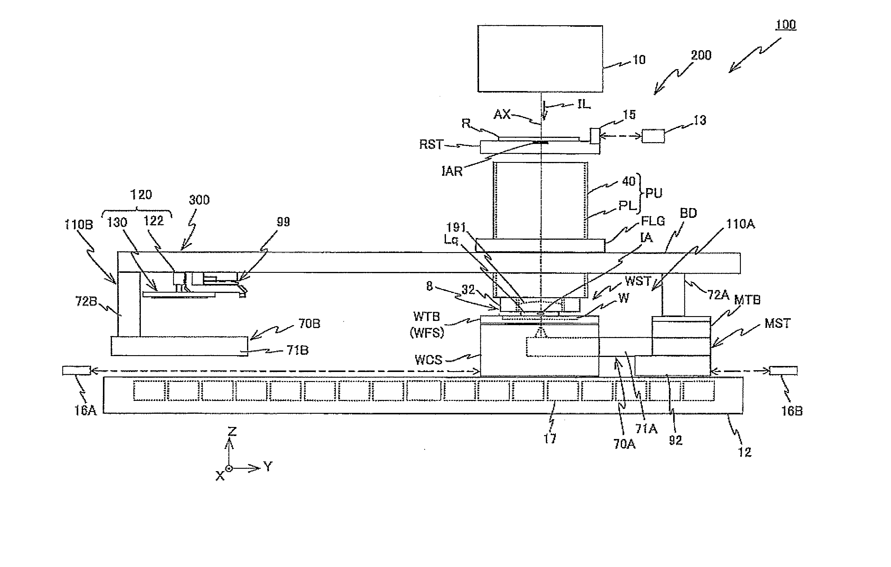
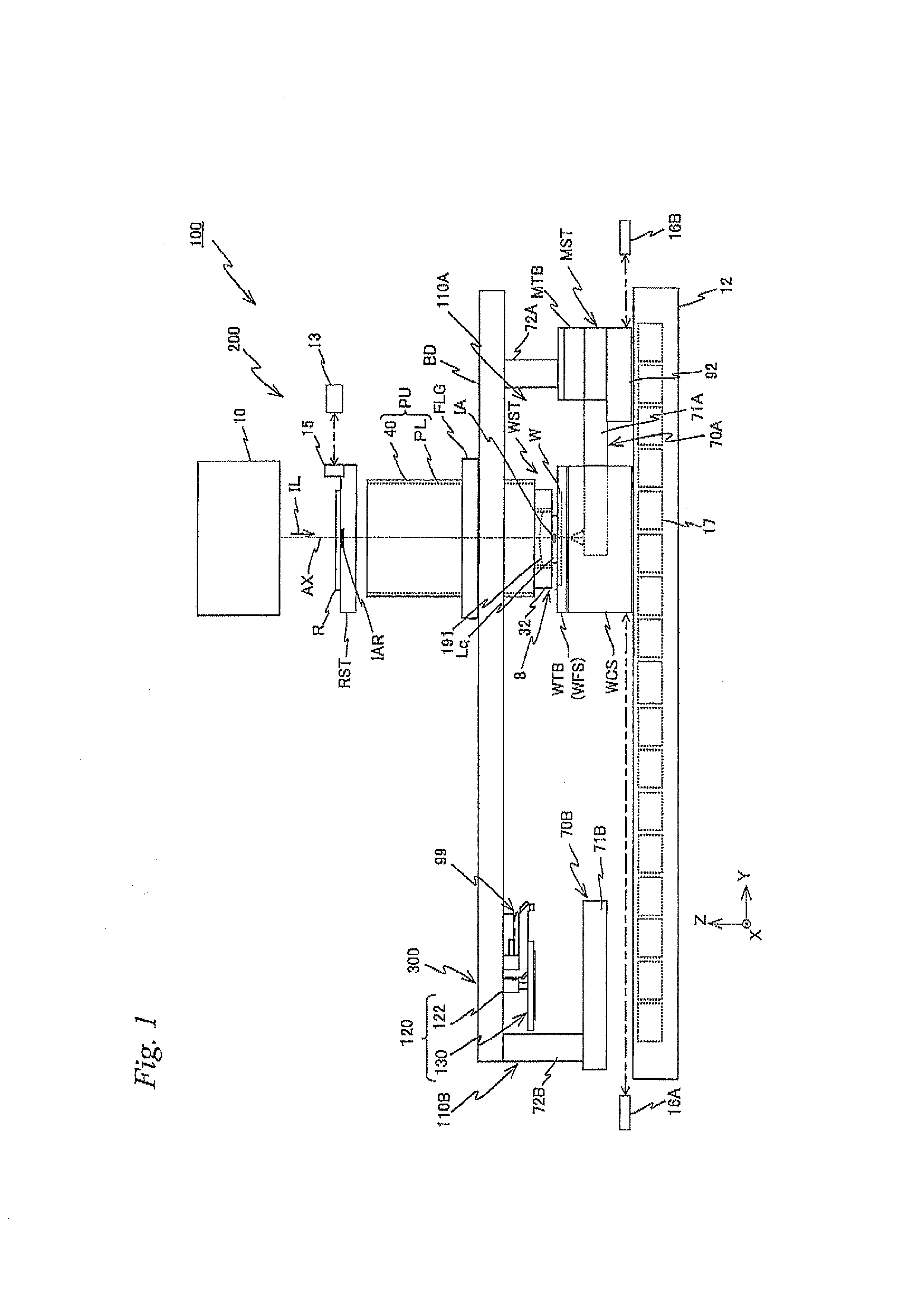
[0292]The first unloading slider driving system 180A and the second unloading slider driving system 180B are controlled by main controller 20 (refer to FIG. 16). Incidentally, the unloading device is not limited to the structure described above, and may be of any structure as long as it is movable holding wafer W. Further, the unloading position of wafer W is also not limited to the position between projection optical system PL and alignment device 99, and for example, unloading can be performed on the opposite side of projection optical system PL with respect to alignment device 99 as in the second embodiment to be described later on.

[0293]FIG. 16 is a block diagram showing an input / output relation of main controller 20 which mainly structures a control system of exposure apparatus 100 and has overall control over each structuring parts. Main controller 20 includes a workstation for a microcomputer) and the like, and has overall control over each of the sections that structure expo...

first embodiment

[0444]Incidentally, in the embodiment described above, as wafer stage position measurement system 16A, a Hall element sensor similar to middle position measurement system 121, or an encoder system and the like can be used, instead of the interferometer system. That is, in the first embodiment described above, no interferometer systems need to be provided. In this case, it is preferable to provide a measurement system which measures relative position information of coarse movement stage WCS and fine movement stage WFS.

[0445]Incidentally, in the first embodiment described above, instead of unloading position UP1 and standby position UP2 set in between exposure station 200 and measurement station 300, only the unloading position can be set in the vicinity of loading position LP, such as for example, a position having the same Y position as loading position LP and is set apart by a predetermined distance to the −X side. In this case, the unloading position can be set at the same positio...


PUM


Abstract

A carrier system equipped with a fine movement stage holding a mounted wafer and can move along a predetermined plane, a chuck main section which holds the wafer above a predetermined position and can move vertically, and vertical movement pins supporting the wafer held by the chuck main section on the fine movement stage from below when the fine movement stage is positioned at the predetermined position and are vertically movable. A controller drives the chuck main section and the vertical movement pins downward until a lower surface of the wafer comes into contact with the fine movement stage while maintaining a hold state by the chuck main section to the wafer and a support state by the vertical movement pins to the wafer, and when the lower surface of the wafer comes into contact with the fine movement stage, the hold state and the support state are released.

Description

CROSS-REFERENCE TO RELATED APPLICATIONS[0001]This non-provisional application claims the benefit of Provisional Application No. 61 / 581,314 filed Dec. 29, 2011, and Provisional Application No. 61 / 581,347 filed Dec. 29, 2011, the disclosures of which are hereby incorporated herein by reference in its entirety.BACKGROUND OF THE INVENTION[0002]1. Field of the Invention[0003]The present invention relates to carrier methods, exposure methods, carrier systems and exposure apparatuses, and device manufacturing methods, and more particularly to a carrier method in which a thin plate-shaped object is carried to a holding device, an exposure method which uses the carrier method, a carrier system which carries a thin plate-shaped object, and an exposure apparatus which is equipped with the carrier system, and a device manufacturing method using the exposure method and the exposure apparatus.[0004]2. Description of the Background Art[0005]Conventionally, in a lithography process for manufacturin...

Claims


Application Information

Patent Timeline
IPC IPC(8): G03F7/20
CPCG03F7/707G03F7/70133G03F7/2041G03F7/70725G03F7/7075G03F9/7088H01L21/6838
Inventor SHIBAZAKI, YUICHI
Owner NIKON CORP
Learn More