Drawing press with stable metal sheet holder

Inactive Publication Date: 2013-07-18
SCHULER PRESSEN GMBH & CO KG
View PDF4 Cites 8 Cited by
  • Summary
  • Abstract
  • Description
  • Claims
  • Application Information

AI Technical Summary

Benefits of technology

[0015]The press concept presented herewith permits the continued use of existing tool sets which had been provided for operation with a stationary die and a metal sheet holder that is moved downwardly during the drawing procedure. Also, the conventional transfer arrangements may be used without essential adaptation changes. With the drawing press according to the invention the linearly movable table may have a group of passages through which support elements extend. These support elements, for example, in the forms of straight bolts, extend through these passages and support the metal sheet holder at a support area. The support area is preferably arranged fixed with respect to the press frame. This means t

Problems solved by technology

Since it has been recognized that with this concept at the drawing cushion a large amount of energy is used and generally

Method used


Image

  • Drawing press with stable metal sheet holder
  • Drawing press with stable metal sheet holder
  • Drawing press with stable metal sheet holder

Examples


Embodiment Construction

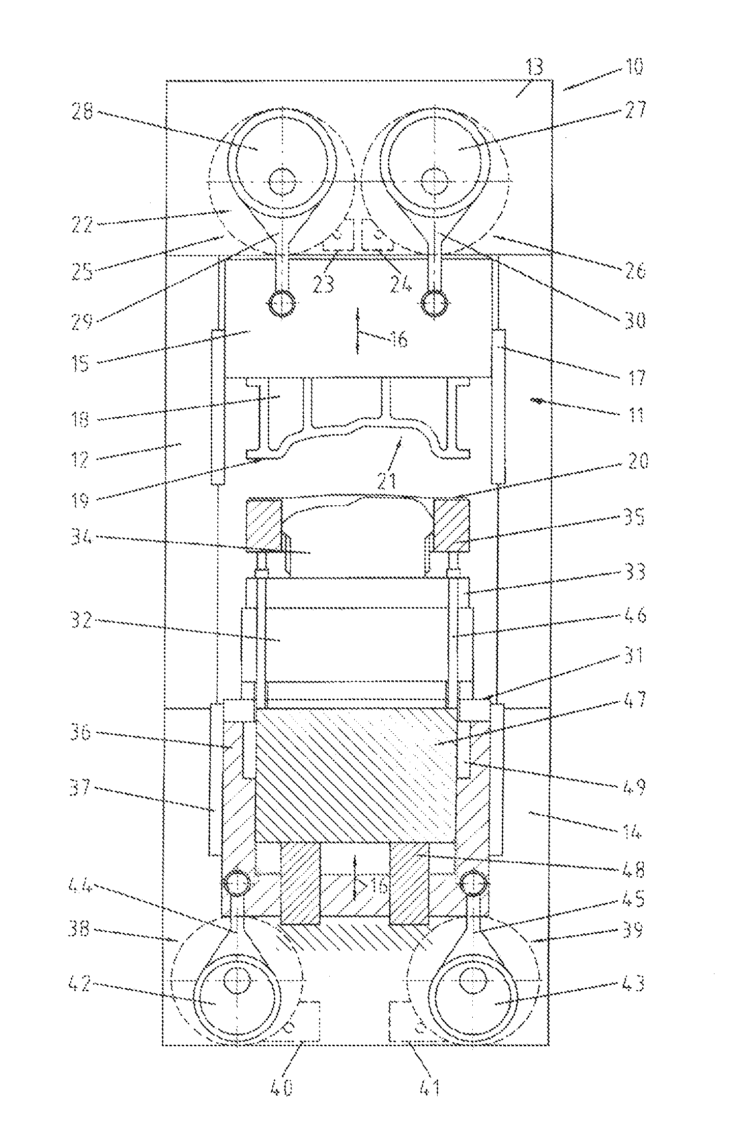
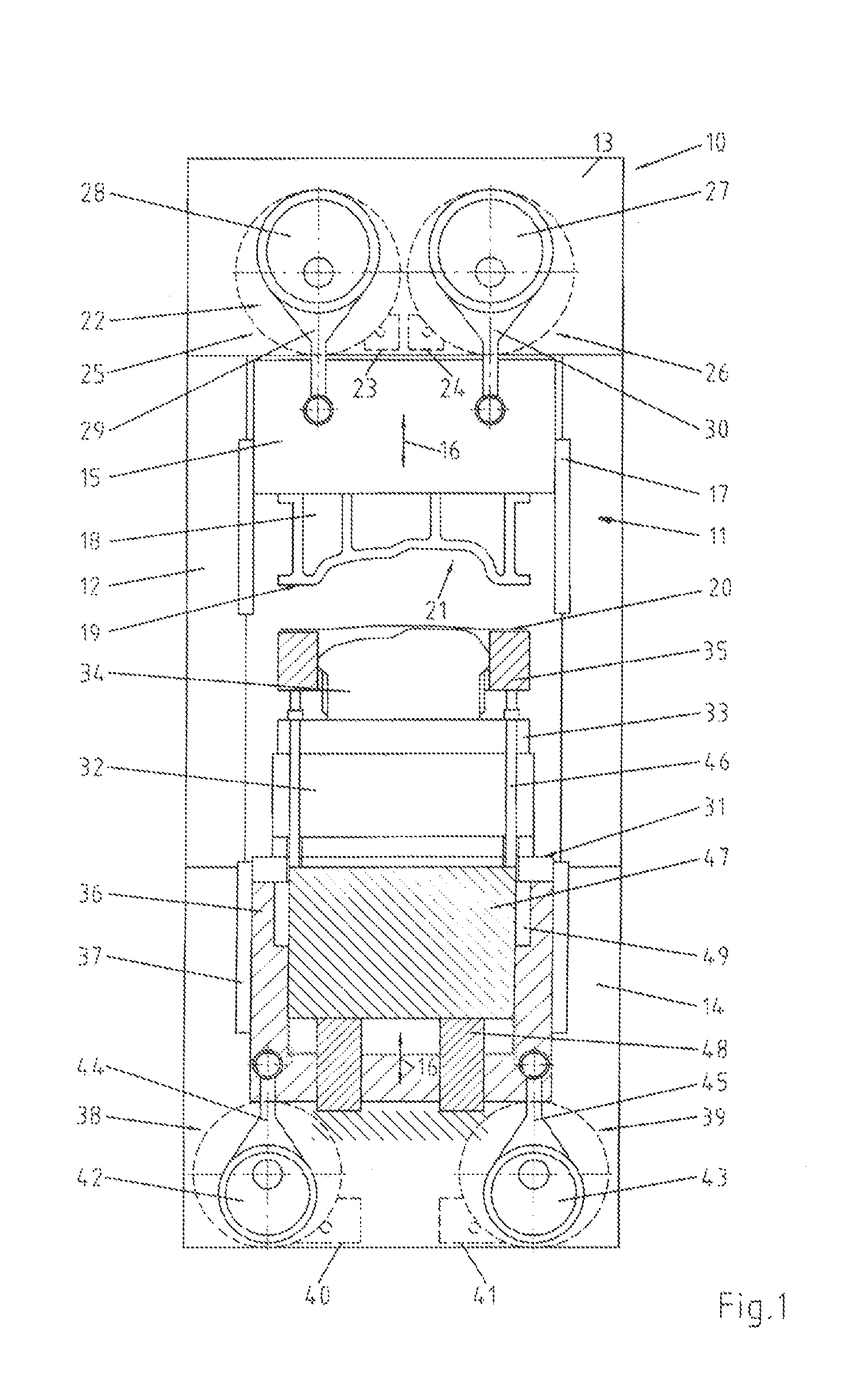
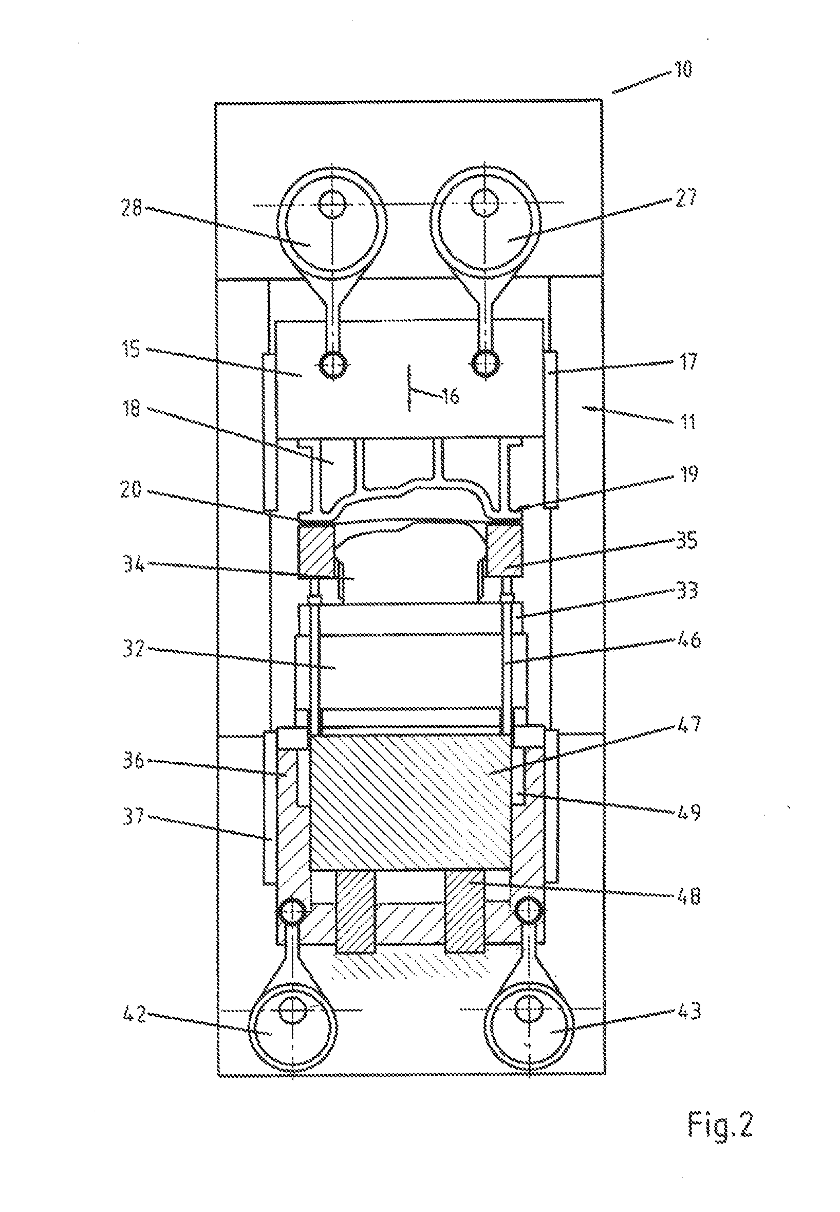
[0029]FIG. 1 shows a drawing press 10 for the manufacture of large metal sheet parts such as vehicle body parts. The drawing press 10 includes a press frame 11 which comprises at least one, preferably several, preferably vertically oriented posts 12, a head 13 which is supported by the parts 12, and a base 14 which is arranged below or between the posts 12. The head 13, the posts 12 and the base 14 form a closed frame. Within this frame a plunger 15 is supported so as to be movable, for example, in a vertical direction 16. For supporting the plunger 15, the posts 12 are provided, for example, with linear guide structures 17.

[0030]The plunger 15 is designed for the accommodation of an upper tool part in the form of a die tool 18. It is shown in FIG. 1 in cross-section and has a rim 19 for clamping and retaining the rim of a workpiece during the drawing procedure. The workpiece is an originally flat metal sheet 20. The rim 19 surrounds a hollow space 21 of the tool into which the work...


PUM


Abstract

The drawing press according to the invention includes a support structure for supporting a metal sheet holder which is part of a tool and supported on the press frame via the support structure. The metal sheet holder is assigned a plunger with a die tool, whereas the plunger is moved by means of a plunger drive which includes a blocking position. The blocking position is obtained, for example, by a drive which, in the locking position does not transmit any movement of the drive output to the driving servomotor. This can be achieved, for example, by an eccentric drive in the stretched position thereof. For performing the actual drawing stroke, the stamping tool is vertically movably supported. A carriage is raised or lowered by the press table by means of a table drive. As table drive, preferably a servomotor with a non-linear drive, such as an eccentric drive is used.

Description

CROSS-REFERENCE TO RELATED APPLICATION[0001]This is a continuation-in-part application of pending international application PCT / EP2011 / 064043 filed Aug. 15, 2011 and claiming the priority of German Application No. 10 2010 034 518.0 filed Aug. 15, 2010 and the priority of German Application No. 10 2010 037 950.6-14 filed Oct. 4, 2010.BACKGROUND OF THE INVENTION[0002]The invention resides in a drawing press which is suitable in particular for integration into press working lines, hybrid press set ups or transfer presses for the manufacture automobile body parts.[0003]In the manufacture of automobile body parts or other large area spatially formed metal sheets the first press stage is generally a drawing press which gives an initially planar plate a spatial shape. This is done in a drawing press in which the rim of the metal sheet is clamped in position or which permits the rim to slide toward the plate center in a controlled manner, while the part of metal sheet surrounded by the shee...

Claims


Application Information

Patent Timeline
IPC IPC(8): B21D24/04B21D53/88
CPCB21D24/00B21D24/04B30B1/14B21D53/88B30B1/266B30B1/28B30B1/18
Inventor SCHOELLHAMMER, DIETMARSCHMEINK, MARTINDANGELMAYR, ANDREASHOFELE, HANSFAHRENBACH, JUERGEN
Owner SCHULER PRESSEN GMBH & CO KG
Why Eureka
Try Eureka