Eureka AIR delivers breakthrough ideas for toughest innovation challenges, trusted by R&D personnel around the world.

Active bearing

a technology of active bearings and bearings, applied in the direction of bearings, shock absorbers, mechanical equipment, etc., can solve the problems of negative effect of vibration decoupling capacity, mechanical structures caused by machines to vibrate in an undesirable manner, and transfer of additional forces, so as to improve the efficiency of actuators

Active Publication Date: 2013-07-18
FRAUNHOFER GESELLSCHAFT ZUR FOERDERUNG DER ANGEWANDTEN FORSCHUNG EV +1
View PDF8 Cites 23 Cited by
  • Summary
  • Abstract
  • Description
  • Claims
  • Application Information

AI Technical Summary

Benefits of technology

The invention is about a new type of bearing that reduces vibrations between two objects. It uses a linear actuator and a gear unit to increase the actuator's efficiency and provide a wide range of frequencies where it can effectively counter the vibrations. The bearing has a simple structure and is designed to be optimized for different vibration tasks or requirements. The gear unit acts as a path enlargement mechanism, reducing the strength requirements on it and the linear actuator. The invention also includes a decoupling unit that separates the static and dynamic loads on the actuator, allowing for a systematic optimization of the bearing properties. Overall, the invention provides an effective and efficient solution for reducing vibrations in various applications.

Problems solved by technology

In numerous technical applications, mechanical structures are caused by machines to vibrate in an undesirable manner.
In order to avoid the vibration amplitudes acting on the elastic bearings becoming unacceptably great, such bearings have a sufficiently high damping capacity, which however can in turn have a negative effect on the capacity for vibration decoupling.
This conflict exists in the case of elastic bearings ultimately leading to a compromise between the highest possible damping of vibrations in the low frequency range and the lowest possible damping vibrations in the higher frequency.
The use of ERF, however, enables only the change in the bearing properties, in particular the stiffness and the damping, but not the transfer of additional forces that counteract the disturbing vibrations.

Method used


Image

  • Active bearing
  • Active bearing
  • Active bearing

Examples


Embodiment Construction

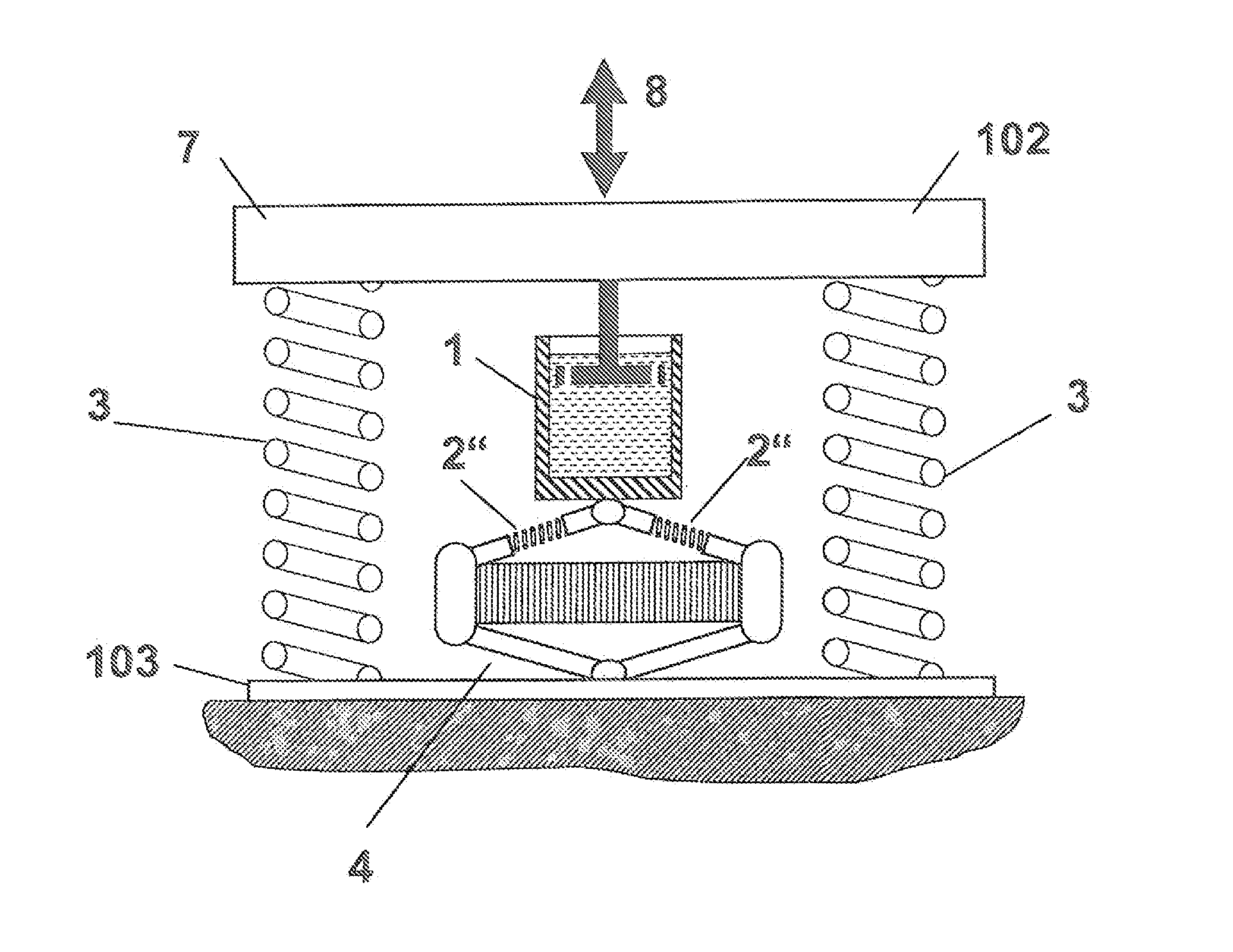
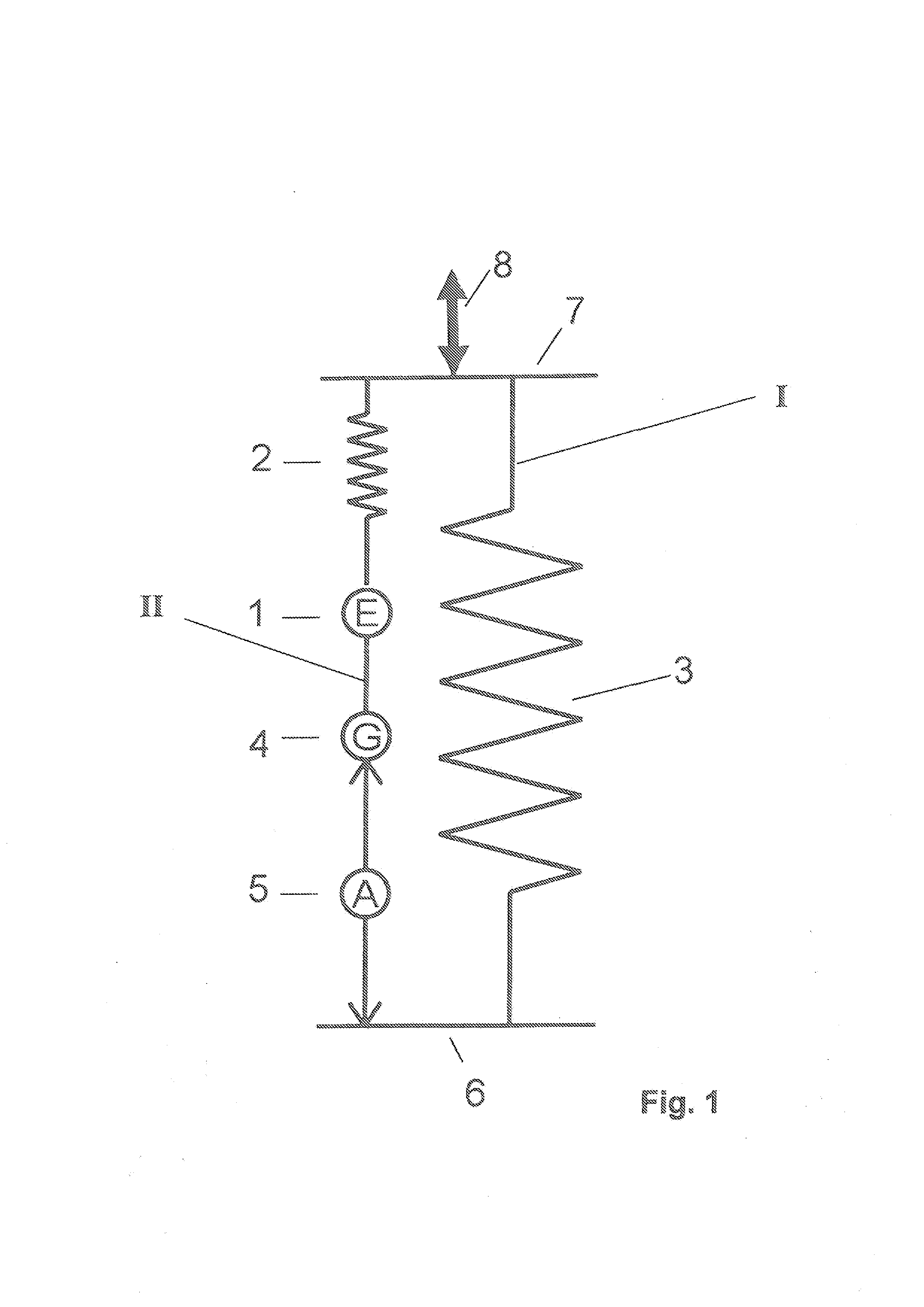
[0035]FIG. 1 illustrates, in a diagrammatic overview, a bearing topology of an active bearing according to the invention. A load 8 encumbered with disturbing vibrations acts at interface 7. The active bearing should be capable of decoupling, as completely as possible, the dynamic component of the load transfer with respect to a support unit 6.

[0036]For this purpose, the active bearing comprises at least two force paths preferably orientated parallel with one another which is a first force path I and a second force path II. Along first force path I, a support element 3 is connected both to interface 7 and also indirectly to support unit 6, which serves to take up the statically acting load component of load 8. The static load component typically originates as a result of the weight force of an object being borne at interface 7, or it may have other or further causes, such as for example driving torques inside a motor-driven vehicle. Support element 3, which typically comprises a susp...


PUM


Abstract

An active bearing at least for vibration reduction is described, comprisinga) an interface (7) to be fitted to a load (8);b) at least one support element (3) in an operative connection with the interface (7) and a support unit (6);c) at least one linear actuator (5) supported indirectly or directly on the support unit (6);d) a gear unit (4) for the path transmission of an actuating path change originating from the linear actuator (5), said gear unit being in an operative connection with the at least one linear reactor (5);e) at least one decoupling unit (1), which serves for the decoupling of the static load transfer and for transmitting the dynamic load transfer; wherein the at least one linear actuator (5), the gear unit (4) and the at least one decoupling unit (1) are disposed serially.

Description

CROSS REFERENCE TO RELATED APPLICATION[0001]Reference is made to Patent Application EP 12 000 216.7, filed on Jan. 16, 2012, which application is incorporated herein by reference in its entirety.BACKGROUND OF THE INVENTION[0002]1. Field of the Invention[0003]The invention relates to an active bearing for the controlled vibration transmission between a vibrating load and a support unit. The active bearing chiefly serves for the vibration reduction, that is the vibration damping and / or vibration decoupling and / or for the vibration compensation of the vibrating load with respect to the support unit. The active bearing is also capable of influencing the vibration state of the vibrating load.[0004]For this purpose, the active bearing comprises an interface to be fitted to the load to be borne with the attributable static and dynamic load transfer acting on the bearing via the interface. To support the static load transfer, typically caused by the weight force of the load, at least one su...

Claims


Application Information

Patent Timeline
IPC IPC(8): F16H21/44
CPCF16H21/44F16F13/264Y10T74/1892Y10T74/18968F16F15/005
Inventor KRAUS, ROMANJUNGBLUT, TIMOHEROLD, SVENMELZ, TOBIAS
Owner FRAUNHOFER GESELLSCHAFT ZUR FOERDERUNG DER ANGEWANDTEN FORSCHUNG EV
Why Eureka
Eureka Blog
Learn More