
Carbon dioxide supply for injection-molding systems

Inactive Publication Date: 2013-07-18
LINDE AG
View PDF6 Cites 4 Cited by
  • Summary
  • Abstract
  • Description
  • Claims
  • Application Information

AI Technical Summary

Benefits of technology

The invention provides a method for delivering liquid carbon dioxide to a sink without any evaporation during transport. The liquid carbon dioxide is first taken from a tank at a low pressure and temperature, and then increased in pressure to make it subcooled. This prevents the carbon dioxide from boiling and ensures its liquid form at the sink. The increase in pressure can be achieved using a pneumatically or hydraulically operated compressor, or an electrically operated heater. The heating of the carbon dioxide is done to a specific temperature range to avoid condensation at atmospheric pressure. The use of an electrically operated heater with precise temperature control also prevents evaporation of the liquid carbon dioxide when no flow is present.

Problems solved by technology

Moisture or water droplets dripping into the injection molds actually affect the quality of the moldings produced and risks corrosion of the molds.
If, by way of example in summer, the temperature in the production building is higher than the boiling point corresponding to the tank pressure, some of the carbon dioxide can evaporate before it leaves the pipeline connecting the medium-pressure tank to the mold, the result of this being poorer and less uniform cooling.

Method used


Image

  • Carbon dioxide supply for injection-molding systems
  • Carbon dioxide supply for injection-molding systems
  • Carbon dioxide supply for injection-molding systems

Examples


Embodiment Construction

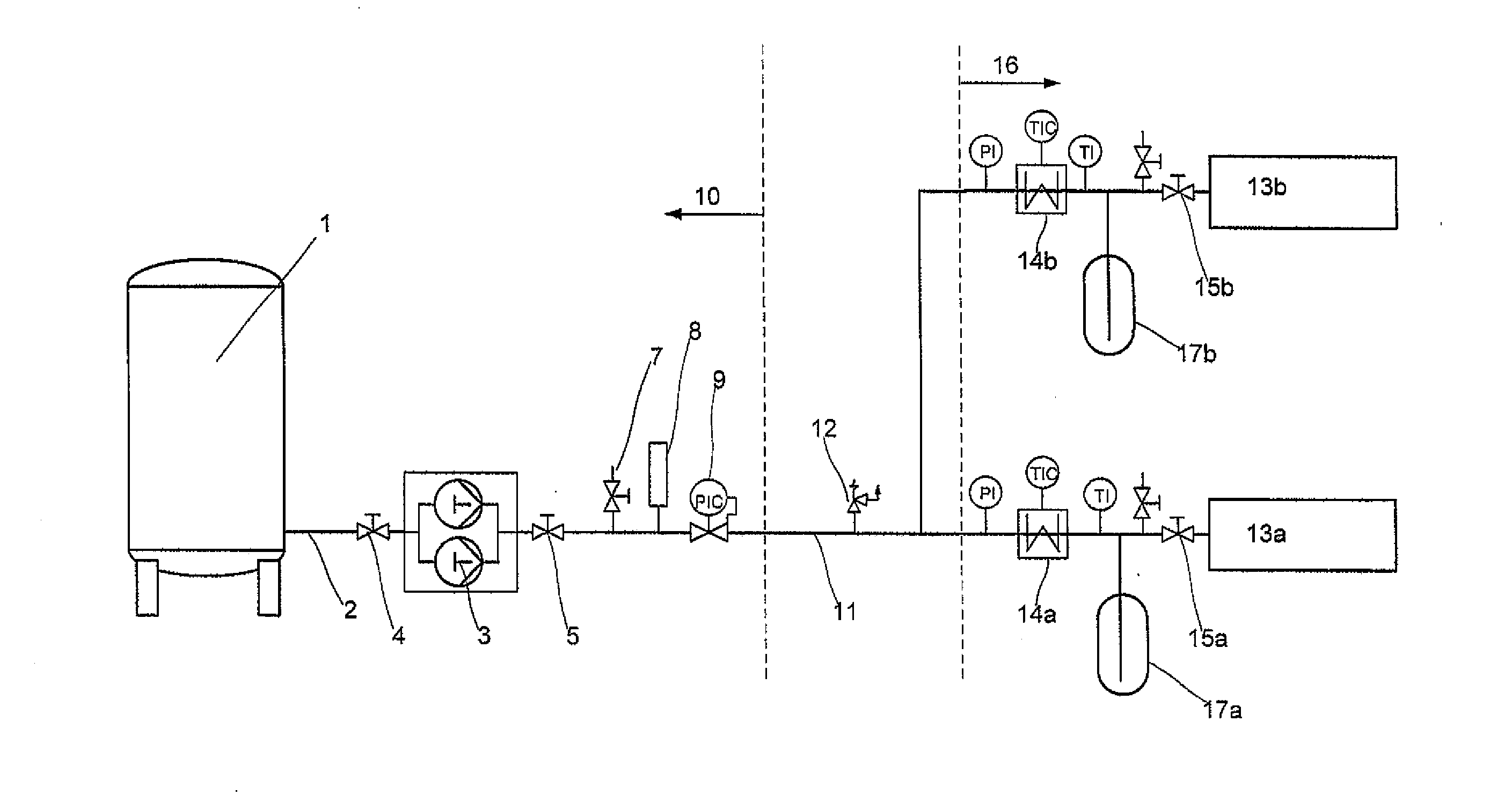
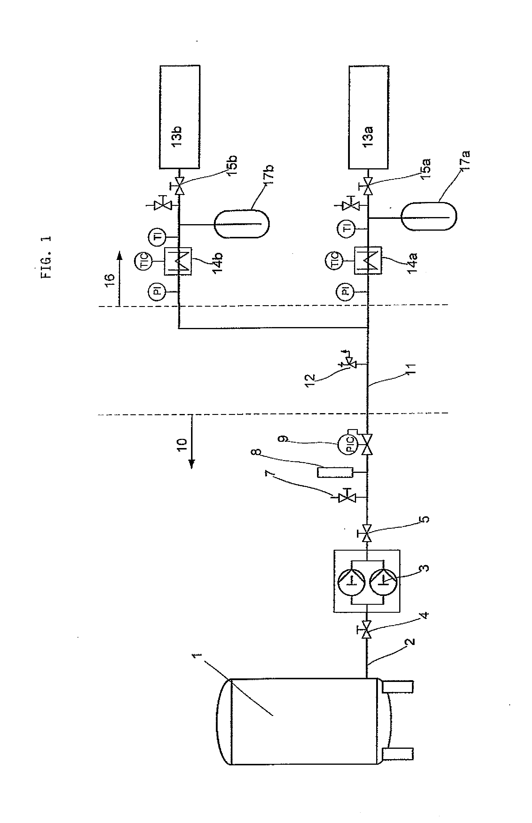
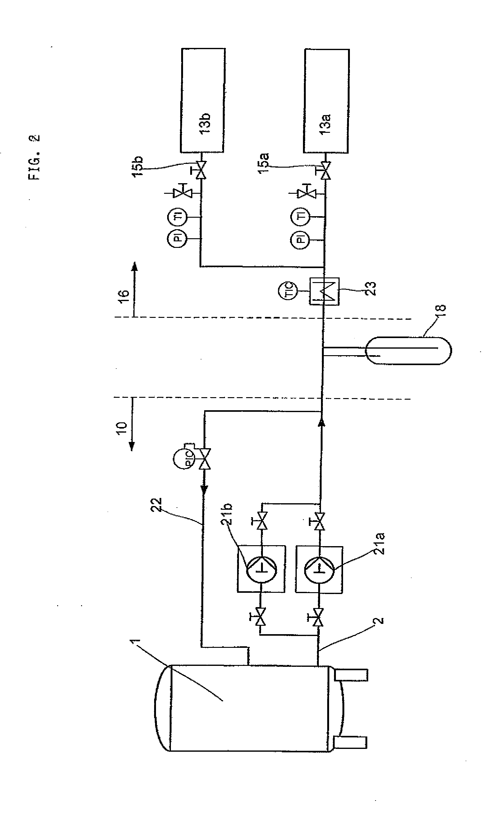
[0025]Each of FIGS. 1 and 2 shows an apparatus for supplying molds, in particular injection molds or injection-molding machinery, with liquid carbon dioxide. The liquid carbon dioxide is needed for cooling the injection molds.

[0026]FIG. 1 shows an apparatus operating by the inventive method. In a low-pressure tank 1 liquid carbon dioxide is stored with a pressure of 20 bar and with a corresponding boiling point of about −20° C. Tank 1 has been designed as a vacuum-insulated tank, but can also have foam insulation. At the lower end of the tank 1 an extraction line 2 has been attached, by way of which liquid carbon dioxide can be taken from the tank 1.

[0027]Connected to the extraction line 2 there is a compressor unit 3. Prior to and behind the compressor unit 3 there are respectively valves 4, 5 installed. By means of the compressor unit 3, carbon dioxide drawn off from the tank 1 is compressed to an elevated pressure of from 40 to 90 bar, preferably from 50 to 70 bar.

[0028]Downstrea...


PUM

PropertyMeasurementUnit
Temperatureaaaaaaaaaa

Abstract

For supplying a sink with liquid carbon dioxide with a required temperature of more than 0° C. and with a required pressure of more than 30 bar, liquid carbon dioxide is taken from a tank, in which it has been stored at a temperature below the required temperature and at a pressure below the required pressure. The pressure of the carbon dioxide is increased and then the carbon dioxide is heated to the required temperature.

Description

CROSS REFERENCE TO RELATED APPLICATIONS[0001]This application is a continuation in part of U.S. patent application Ser. No. 11 / 794,408 filed Mar. 19, 2008 which claims priority from International Patent Application No. PCT / EP20061000143, filed Jan. 10, 2006, claiming priority from German Patent Application No. 1020050029, filed Jan. 21, 2005.BACKGROUND OF THE INVENTION[0002]The invention relates to a method for supplying a sink with liquid carbon dioxide with a required temperature of more than 0° C. and with a required pressure of more than 30 bar. The invention moreover relates to an apparatus for supplying a sink with liquid carbon dioxide under the conditions mentioned.[0003]Carbon dioxide is one of the materials used for cooling of injection molds. To this end, capillary tubes or expansion nozzles are supplied with liquid carbon dioxide free from bubbles, and this expands in the capillary tubes and thus withdraws heat from the injection mold.[0004]For uniform and reproducible c...

Claims


Application Information

Patent Timeline
IPC IPC(8): F17C5/02
CPCF17C5/02F17C9/00F17C2201/032F17C2201/054F17C2201/056F17C2203/0329F17C2203/0391F17C2205/018F17C2221/013F17C2223/0169F17C2225/013F17C2225/035F17C2225/036F17C2227/0135F17C2227/0157F17C2227/0304F17C2250/01F17C2250/043F17C2250/0626F17C2270/05
Inventor PRALLER, ANDREAS
Owner LINDE AG
Learn More