Apparatus and method for receiving and transporting real time energy data

a technology of real-time energy data and apparatus, applied in the direction of wireless communication, wireless architecture usage, instruments, etc., can solve the problems of inaccuracy of readings, laborious and consequently high cost, and the billing based on consumption

Active Publication Date: 2013-07-18
ENEL X NORTH AMERICA INC
View PDF9 Cites 67 Cited by
  • Summary
  • Abstract
  • Description
  • Claims
  • Application Information

AI Technical Summary

Benefits of technology

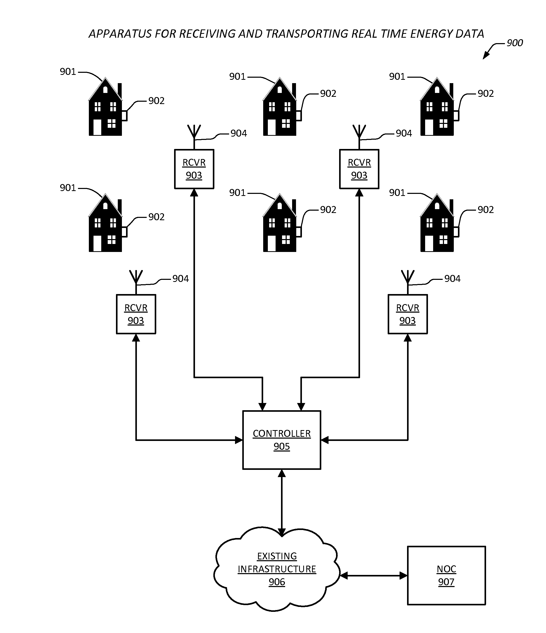
[0023]The present invention, among other applications, is directed to solving the above-noted problems and addresses other problems, disadvantages, and limitations of the prior art. The present invention provides a superior technique for receiving and transporting real time resource usage data corresponding to a grid of resource usage devices that employ a frequency hopping algorithm to broadcast usage data. In one embodiment, an apparatus is provided for receiving and transporting real time resource usage data. The apparatus includes a plurality of narrowband receivers and a controller. The plurality of narrowband receivers is deployed geographically within a grid, where each of the plura

Problems solved by technology

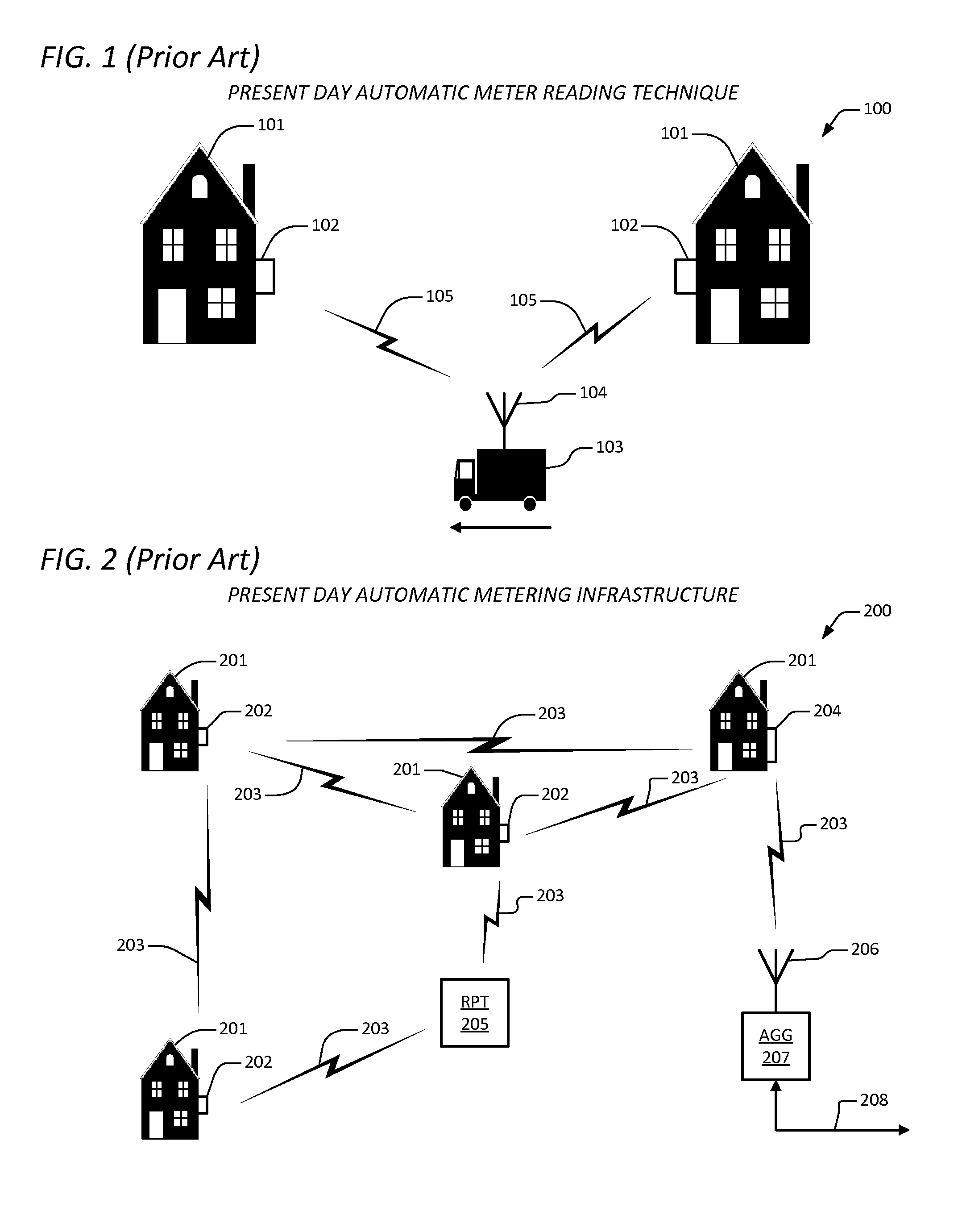
And not long after larger distribution grids were deployed by these utilities, the problem of billing based upon consumption arose.
This manner of obtaining usage data, however, was labor intensive and consequently very costly.
In addition, because the act of reading a meter involved interpretation of the meaning of one or more visual indicators (typically analog indicators like the hands on a watch), these readings were subject to inaccuracies due to errors made by the meter readers.
But in order to deploy AMR products, the resource providers had to completely replace their existing inventory of meters—literally hundreds of millions of meters—at substantial expense, the bulk of which was conveyed

Method used


Image

  • Apparatus and method for receiving and transporting real time energy data
  • Apparatus and method for receiving and transporting real time energy data
  • Apparatus and method for receiving and transporting real time energy data

Examples


Embodiment Construction

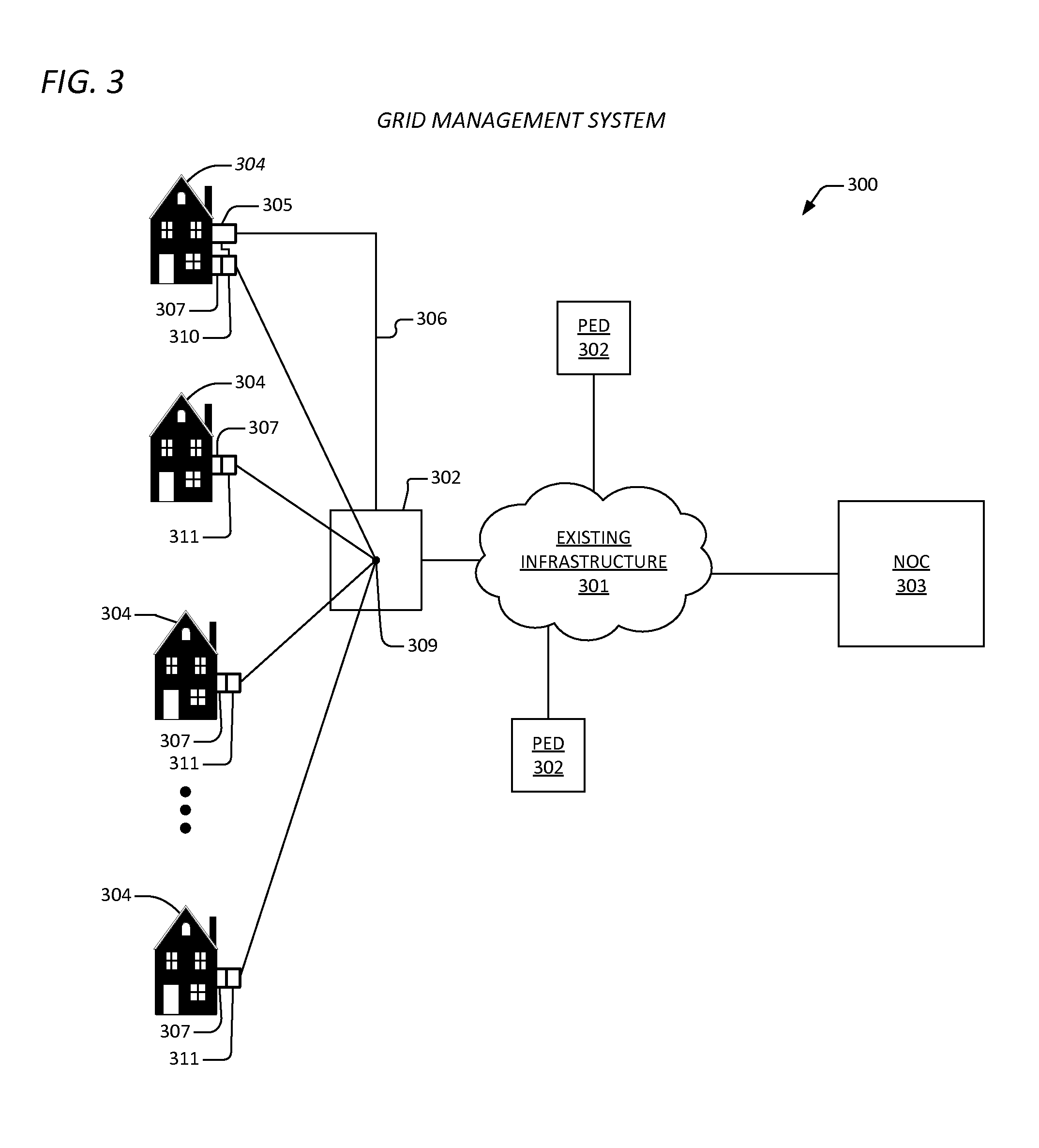
[0049]Exemplary and illustrative embodiments of the invention are described below. In the interest of clarity, not all features of an actual implementation are described in this specification, for those skilled in the art will appreciate that in the development of any such actual embodiment, numerous implementation-specific decisions are made to achieve specific goals, such as compliance with system related and / or business related constraints, which vary from one implementation to another. Furthermore, it will be appreciated that such a development effort might be complex and time-consuming, but would nevertheless be a routine undertaking for those of ordinary skill in the art having the benefit of this disclosure. Various modifications to the preferred embodiment will be apparent to those skilled in the art, and the general principles defined herein may be applied to other embodiments. Therefore, the present invention is not intended to be limited to the particular embodiments show...


PUM


Abstract

An apparatus is provided for receiving and transporting real time resource usage data. The apparatus includes a plurality of narrowband receivers and a controller. The a plurality of narrowband receivers is deployed geographically within a grid, where each of the plurality of narrowband receivers is configured to receive transmissions from a least one of a plurality of transmitting devices, and where each of the plurality of transmitting devices transmits identical data on each of a plurality of frequency bands that are hopped according to a hopping sequence. The controller is coupled to the plurality of narrowband receivers, and is configured to control the plurality of narrowband receivers such that the each of the plurality of transmitting devices is identified, and is configured to control the plurality of receivers such that corresponding data from the each of the transmitting devices is received on at least one of the plurality of frequency bands.

Description

CROSS-REFERENCE TO RELATED APPLICATIONS[0001]This application claims the benefit of the following U.S. Provisional Application, which is herein incorporated by reference for all intents and purposes.SERIALFILINGNUMBERDATETITLE61534503Sep. 14, 2011WIRELESS NETWORK(ENER.0106)EXTENSIONS FORENERGY MANAGEMENTAND DEMAND CONTROL[0002]This application is related to the following co-pending U.S. patent applications, both of which are herein incorporated by reference for all intents and purposes.SERIALFILINGNUMBERDATETITLE13025142Feb. 10, 2011APPARATUS AND METHOD(ENER.0101)FOR DEMAND COORDINATIONNETWORK13032622Feb. 22, 2011APPARATUS AND METHOD(ENER.0103)FOR NETWORK-BASEDGRID MANAGEMENTBACKGROUND OF THE INVENTION[0003]1. Field of the Invention[0004]This invention relates in general to the field of automated resource control, and more particularly to an apparatus and method for receiving and transporting real time energy data from automated meter reading (AMR) utility meters.[0005]2. Descriptio...

Claims


Application Information

Patent Timeline
IPC IPC(8): G08C15/02H04W4/80
CPCH04Q9/00H04Q2209/60H04Q2209/43G08C15/02H04Q2209/50H04B1/7156H04B2001/71563H04W4/80G01D4/002H04W12/08Y04S20/30H04L41/12H04W24/06H04W84/18H04W24/08H04L63/06H04L63/10
Inventor WILLIG, RANDY C.JONES, MORGANMATHEWS, JEFFREY P.
Owner ENEL X NORTH AMERICA INC
Why Eureka
Try Eureka