System and method for calibrated spectral domain optical coherence tomography and low coherence interferometry

Inactive Publication Date: 2013-07-18
THE BRIGHAM & WOMEN S HOSPITAL INC
View PDF1 Cites 64 Cited by
  • Summary
  • Abstract
  • Description
  • Claims
  • Application Information

AI Technical Summary

Benefits of technology

[0014]It is yet another aspect of the invention to provide a method for producing an image of a subject with an OCT system. At least one of a reference path and a sample path, which is in optical communication with the subject, of the OCT system are illuminated with a light source. An interference signal is then identified from the reference and sample paths of the OCT system, and a calibration signal acquired from light emitted by the light source. The calibration signal may be amplified with a logarithmic amplifier to produce an amplified calibration signal that is more robust to phase errors and to fluctuations in the original calibration signal. A series of extr

Problems solved by technology

This method can dynamically compensate the instability of the starting point of the sweeping but requires high repeatability of the spectrum.
Balanced detection techniques are not easily implemented in the FP method, which leads to more phase errors in the calibration signal, as well as the potential for excess noise.
Poor or imprecise calibration could significantly degrade the system performance in terms of the resolution and the ranging accuracy, as well as other parameters.
This can reduce the time consumption of software calibration, but increases the overall cost as the electronics are more complex, and is not feasible for different operation frequencies of the source.
However, the power of any selected wavelength component is always much lower than the total power, which is a drawback of this approach.
Moreover, a complex tuning/scanning mechanism is required for precise and repeatable functioning.
Even in this more common approach, however, the issue of a complex tuning mechanism is present as a drawback.

Method used


Image

  • System and method for calibrated spectral domain optical coherence tomography and low coherence interferometry
  • System and method for calibrated spectral domain optical coherence tomography and low coherence interferometry
  • System and method for calibrated spectral domain optical coherence tomography and low coherence interferometry

Examples


Embodiment Construction

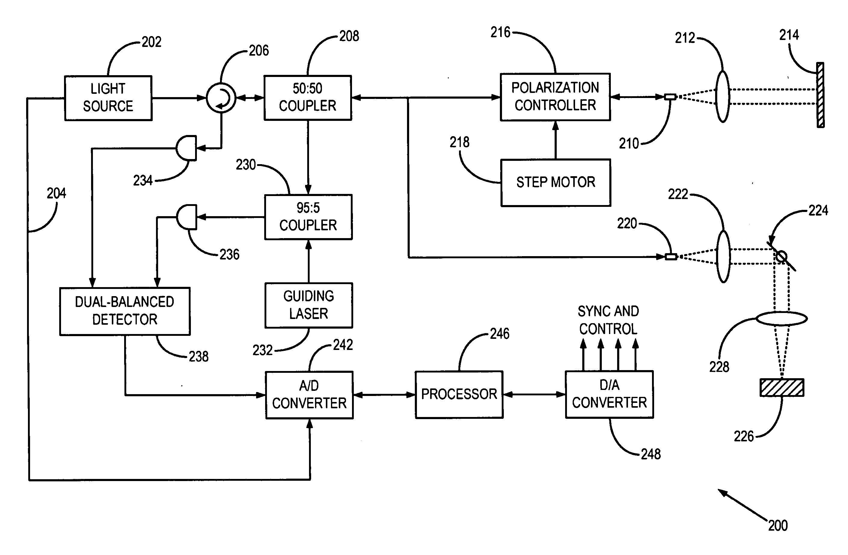
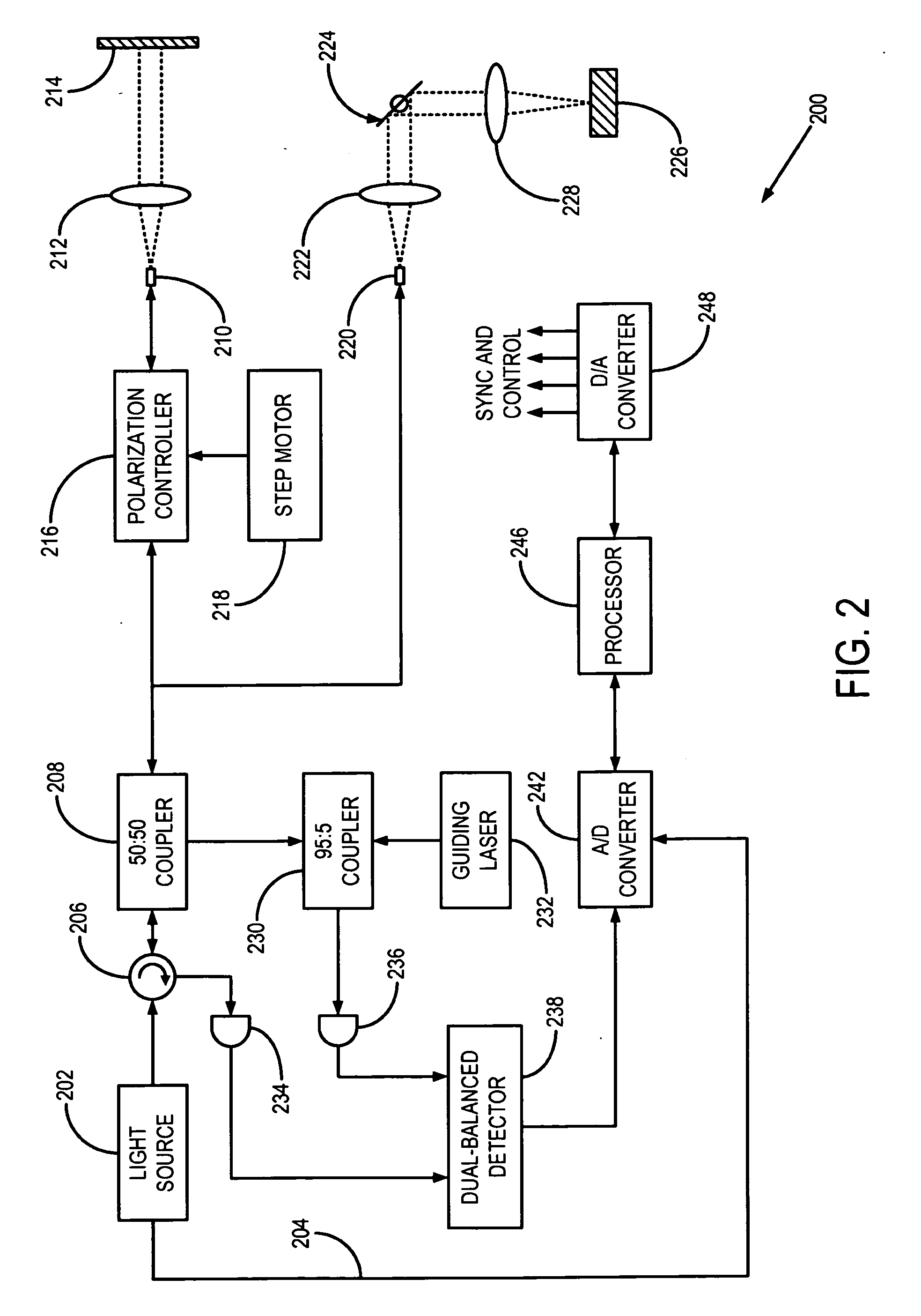
[0027]The theoretical analysis of a spectral-domain (“SD”) optical coherence tomography (“OCT”) system, such as a swept-source OCT (“SS-OCT”) or Fourier domain OCT (“FD-OCT”) system, is based, for example, on a free-space Michelson interferometer. This simplification generally holds regardless of the differences in interferogram measurement or whether the system is configured in free space or fiber-optically, and whether a different interferometer is employed. While reference is made herein to OCT systems and methods, it will be appreciated by those skilled in the art that the systems and methods are also applicable for low coherence interferometry.

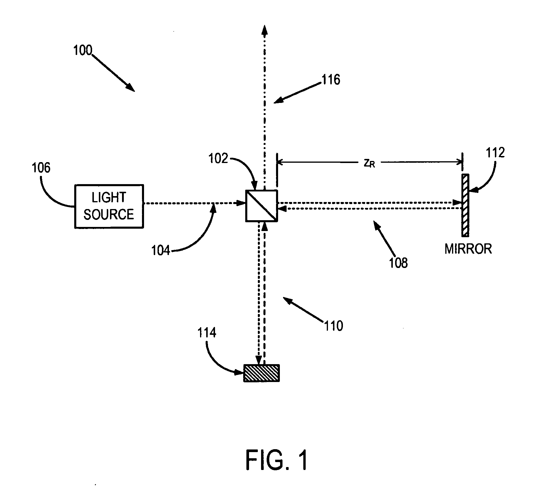
[0028]An exemplary configuration of a free-space Michelson interferometer 100 is depicted in FIG. 1, to which reference is now made. A coupler 102 that also acts as a beam splitter, such as a 50:50 beam splitter, divides a light beam 104 from a light source 106 into a reference arm 108 and a sample arm 110 of the interferometer 100. In th...


PUM


Abstract

Systems and methods for enhancing spectral domain optical coherence tomography (OCT] are provided. In particular, a system and method for calibration of spectral interference signals using an acquired calibration signal are provided. The calibration signal may be logarithmically amplified to further improve the accuracy of the calibration. From the calibration signal, a series of more accurate calibration data are calculated. An acquired spectral interference signal is calibrated using these calibration data. Moreover, systems that include logarithmic amplification of the spectral interference signal and variable band-pass filtering of the spectral interference signal are provided. Such systems increase the dynamic range and visualization capabilities relative to conventional spectral domain OCT systems.

Description

CROSS-REFERENCE TO RELATED APPLICATIONS[0001]This application claims the benefit of U.S. Provisional Patent Application Ser. No. 61 / 265,571, filed on Dec. 1, 2009, and entitled “SYSTEM AND METHOD FOR ENHANCED SPECTRAL DOMAIN OPTICAL COHERENCE TOMOGRAPHY AND LOW COHERENCE INTERFEROMETRY”.STATEMENT REGARDING FEDERALLY SPONSORED RESEARCH[0002]This invention was made with United States Government support awarded by the following agency: National Institutes of Health NIH AR44812, NIH HL55686, NIH EB02638 / HL63953, NIH AR46996, and NIH EB00419. The United States Government has certain rights in this invention.FIELD OF THE INVENTION[0003]The field of the invention is systems and methods for optical coherence tomography (“OCT”) and low coherence interferometry (“LCI”). More particularly, the invention relates to systems and methods for enhanced spectral domain OCT and LCI.BACKGROUND OF THE INVENTION[0004]Optical coherence tomography (“OCT”), which is based on low coherence interferometry, me...

Claims


Application Information

Patent Timeline
IPC IPC(8): G01B9/02
CPCA61B5/0066A61B5/7257G01N21/4795G01B9/02074G01B9/02044G01B9/02091G01N2021/1787
Inventor BREZINSKI, MARKLIU, BINAZIMI, EHSAN
Owner THE BRIGHAM & WOMEN S HOSPITAL INC
Why Eureka
Try Eureka