

Infrared Fixed-Focus Lens
- Summary
- Abstract
- Description
- Claims
- Application Information
AI Technical Summary
Benefits of technology
Problems solved by technology
Method used
Image

Examples
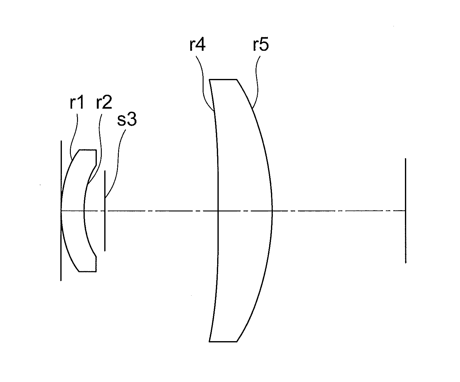
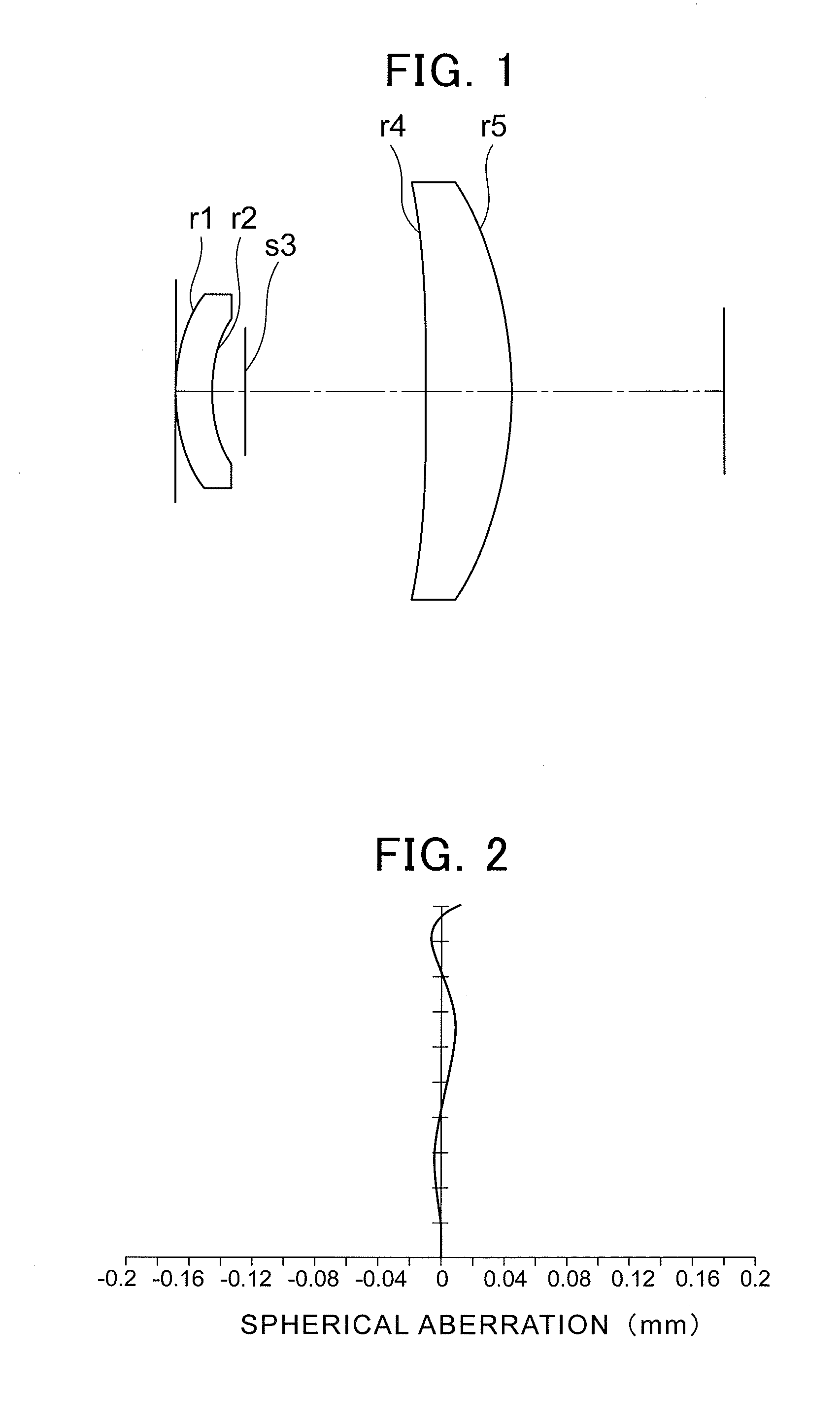
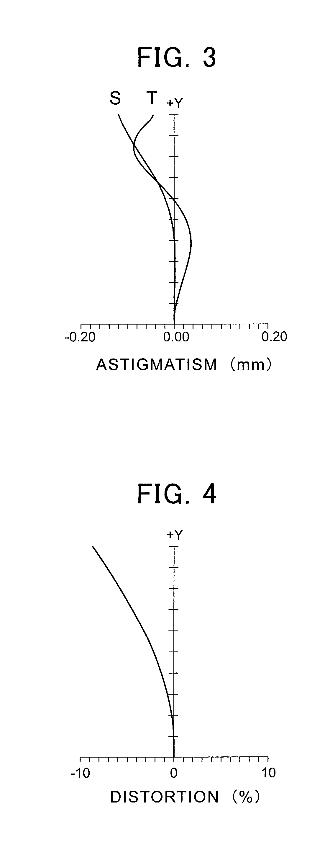
embodiment 1
[0048]
Focal Length 8.4 mmF num. F / 1.0Angle of Field 2ω = 50°CurvatureDistance between AdjacentLensSurface #of RadiusLens Pieces / Lens ThicknessMaterial1 (ASPH)28.11982.5000Germanium2 (ASPH)18.48482.00023 (STOP)12.09054 (ASPH)−366.61506.0000Germanium5 (ASPH)−28.140413.9190
[0049]Aspheric surfaces can be expressed as in the following formula (3):
X=H2 / R1+1-(ɛH2 / R2)+AH2+BH4+CH6+DH8+EH10(3)
where X is an aspherized shape, R is a curvature of radius, ε is a conic constant, and H is a height from the optical axis (in millimeters).
[0050]Coefficients, A, B, C, D and E, for the aspheric surfaces as expressed by the formula take their respective values as follows:
Surface #0 (EP)2 (A)4 (B)6 (C)8 (D)10 (E)11.00000.0000E+004.8636E−04−2.0284E−062.7596E−08 2.9694E−1021.00000.0000E+007.7063E−04 8.9604E−06−2.9221E−07 1.7511E−0841.00000.0000E+00−1.4004E−05 −9.9035E−088.7376E−10−2.4866E−1251.00000.0000E+008.0977E−06−9.9537E−085.9356E−10−1.4124E−12
[0051]The value related to formulae (1) is given as f...
embodiment 2
[0053]
Focal Length 8.34 mmF num. F / 1.0Angle of Field 2ω = 49.66°CurvatureDistance between AdjacentLensSurface #of RadiusLens Pieces / Lens ThicknessMaterial1 (ASPH)15.06962.5000Germanium2 (ASPH)11.49992.00023 (STOP)11.26544 (ASPH)331.49166.0000Germanium5 (ASPH)−28.183410.7824
[0054]Coefficients, A, B, C, D and E, for the aspheric surfaces as expressed by the formula take their respective values as follows:
Surface #0 (EP)2 (A)4 (B)6 (C)8 (D)10 (E)11.00000.0000E+003.5965E−043.8914E−06 −1.0751E−07 2.6374E−0921.00000.0000E+007.2485E−042.6149E−05−1.2666E−06 6.2477E−0841.00000.0000E+00−2.5357E−05 −9.5073E−08 8.5019E−10−2.0664E−1251.00000.0000E+008.3342E−06−1.2120E−07 6.1565E−10 −1.2373E−12
[0055]The value related to formulae (1) is given as follows: f1 / f=−4.070
[0056]The value related to formulae (2) is determined as follows: d / f=1.590
embodiment 3
[0057]
Focal Length 8.40 mmF num. F / 1.0Angle of Field 2ω = 50.48°CurvatureDistance between AdjacentLensSurface #of RadiusLens Pieces / Lens ThicknessMaterial1 (ASPH)47.50842.5000Germanium2 (ASPH)20.81831.50003 (STOP)14.26834 (ASPH)−104.86206.0000Germanium5 (ASPH)−27.638719.7897
[0058]Coefficients, A, B, C, D and E, for the aspheric surfaces as expressed by the formula take their respective values as follows:
Surface #0 (EP)2 (A)4 (B)6 (C)8 (D)10 (E)11.00000.0000E+006.0412E−04−5.2552E−063.9653E−082.9914E−1021.00000.0000E+008.0092E−04 1.8934E−05−1.0322E−06 2.8721E−0841.00000.0000E+00−6.6122E−06 −1.0390E−078.7916E−10−2.5811E−12 51.00000.0000E+007.5210E−06−9.1623E−085.8044E−10−1.3942E−12
[0059]The value related to formulae (1) is given as follows: f1 / f=−1.580
[0060]The value related to formulae (2) is determined as follows: d / f=1.877
PUM
 Abstract
Description
Claims
Application Information