Method and system for hybrid coherent and incoherent diffractive beam combining

a diffractive beam and hybrid technology, applied in electromagnetic transmission, transmission, manufacturing tools, etc., can solve the problems of limiting the size of the aperture that can be designed for any optical apparatus, limiting the advancement of high-power laser technology, and limiting the diffraction of laser beams focused to this theoretical limi

Active Publication Date: 2008-10-14
NORTHROP GRUMMAN SYST CORP
View PDF29 Cites 84 Cited by
  • Summary
  • Abstract
  • Description
  • Claims
  • Application Information

AI Technical Summary

Problems solved by technology

A laser beam focused to this theoretical limit is said to be diffraction limited.
Generally speaking, advancement of the art of high power lasers is impeded by physical limitations encountered when attempting to achieve this limit.
However, there are practical limitations on the size of an aperture that can be designed for any optical apparatus.
Imperfections in the optics may cause degradations in the laser wavefront that affect the focus, and in high power applications, thermal variations contribute to the degradation.
This limits the designer's ability to focus the beam, resulting in a focal spot somewhat greater than 1.0 times the diffraction limit (1.0×DL).
At present, the most advanced near-diffraction-limited laser beams cannot deliver enough power per unit area to serve effectively in high-power applications.
However, even in the most tightly packed array, the “fill factor” of the composite beam (ratio of the composite beam power to a beam that uniformly fills the entire array aperture and has equal peak intensity) is only about 70%, due to voids that occur between fibers and also to the Gaussian shape of each beam.
In other words the composite beam has a shape dramatically different than that of the constituent beams, and as a result the composite does not focus as well as the constituents.
While this technique therefore eliminates the fill factor problem associated with the two-dimensional array, other problems arise from using multiple wavelengths.
For one, the complexity of the system increases as each wavelength requires a different oscillator.
Furthermore, the propagation angle of each wavelength must be precisely adjusted such that its incidence on the grating is exact, otherwise the beams will misalign.
However, disadvantages occur when sampling the phases of the high power combined output beams.
A high power beam passing through a transmissive beam splitter causes thermal distortion that affects the phase measurement accuracy and focusability of the output beam.
For a very large number of combined beams the accuracy of phase measurement becomes more difficult with a single detector.

Method used


Image

  • Method and system for hybrid coherent and incoherent diffractive beam combining
  • Method and system for hybrid coherent and incoherent diffractive beam combining
  • Method and system for hybrid coherent and incoherent diffractive beam combining

Examples


Embodiment Construction

[0023]Coherent Diffractive Beam Combining

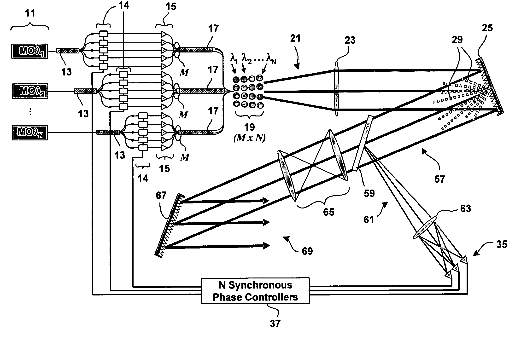
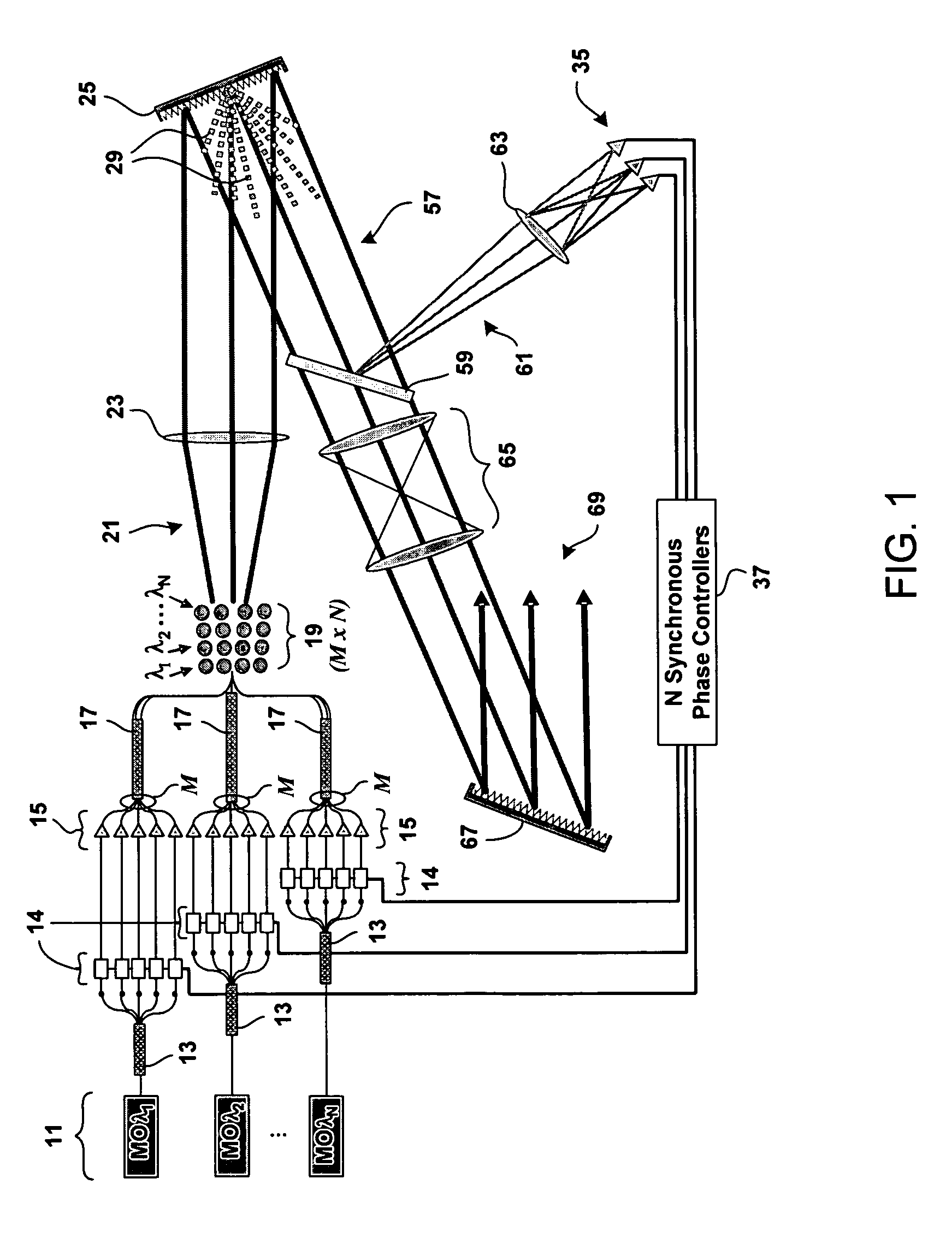
[0024]A coherent diffractive beam combining method has been proposed in co-pending U.S. patent application Ser. No. 11 / 361,352 by inventors named in the present application. In general, the diffractive beam combining method employs a DOE to enable the coherent combination of the output of a plurality of fiber amplifiers transmitting laser beams derived from a common oscillator. The beam combination method requires active phasing of the outputs from the fiber amplifiers to lock the phases of the output beams in order to optimize intensity of the composite beam by means of constructive interference. Active phasing is achieved by placing a beam splitter in the path of the composite beam that is diffracted by the DOE. The beam splitter produces a low power sample of the composite beam, and the sample is focused onto a phase detector. In the phase detector, the output phase of each constituent beam is detected by decoding signals that are encoded ...


PUM

PropertyMeasurementUnit
wavelength spread Δλ/λaaaaaaaaaa
reflectivityaaaaaaaaaa
wavelengthsaaaaaaaaaa

Abstract

A hybrid beam combining system or method combines a plurality of coherent and incoherent light beams into a composite high power diffraction limited beam. N oscillators each transmit light at one of N different wavelengths and each wavelength is split into M constituent beams. M beams in each of N groups are phase locked by a phase modulator using phase correction signals. The phase locked beams are amplified and coupled into an M×N fiber array. Beams emerging from the array are collimated and incident on a diffractive optical element operating as a beam combiner combining the M outputs at each N wavelength into a single beam. The N single beams are incident and spectrally combined on a grating which outputs a composite beam at a nominal 100% fill factor. A low power sample beam, taken from the N beams emerging from the diffractive optical element, is measured for phase deviations from which the phase correction signals are derived and fed back to the phase modulators. The diffractive optical element may include a weak periodic grating for diffracting the low power sample. The diffractive optical element may also be combined with the spectral combining grating into a single optical element.

Description

[0001]This application is related to U.S. patent application Ser. No. 11 / 361,352 filed Feb. 24, 2006; U.S. patent application Ser. No. 11 / 543,677 filed Oct. 5, 2006; U.S. patent application Ser. No. 11 / 543,613 filed Oct. 5, 2006; and U.S. patent application Ser. No. 11 / 543,567 filed Oct. 5, 2006; all of which are fully incorporated herein by reference.BACKGROUND OF THE INVENTION[0002]1. Field of the Invention[0003]The present invention relates to combining light beams using diffractive beam combining in conjunction with a spectral beam combining.[0004]2. Description of Related Art[0005]High power lasers have many possible applications. In a military application, sufficient energy focused in a laser beam can provide an effective defensive countermeasure against ballistic projectiles. In a commercial application, a high power laser can be used to weld metal components that are too thick to be welded by conventional methods. To improve the effectiveness of the laser in any of these app...

Claims


Application Information

Patent Timeline
Patent Type & Authority Patents(United States)
IPC IPC(8): H01S3/00
CPCB23K26/0604B23K26/067B23K26/426H01S3/005H01S3/1307H01S3/2391B23K26/705
Inventor ROTHENBERG, JOSHUA E.RICE, ROBERT R.WICKHAM, MICHAEL G.
Owner NORTHROP GRUMMAN SYST CORP
Why Eureka
Try Eureka