System and method of an integrated fiber optic inspection and cleaning apparatus

a fiber optic inspection and cleaning technology, applied in the direction of optical apparatus testing, instruments, optical elements, etc., can solve the problems of not providing cleaning, not providing inspection probes, and not providing magnification and field of view of the optics used, and achieve rapid and reliable detection, high resolution, and high accuracy.

Active Publication Date: 2013-09-05
FIBERQA
View PDF21 Cites 45 Cited by
  • Summary
  • Abstract
  • Description
  • Claims
  • Application Information

AI Technical Summary

Benefits of technology

[0013]The present disclosure provides a cleaning and inspection system for fiber optics that is rapid and reliable and can be used for various types of fiber optic components, in order to clean ends of optical fibers and in some cases the surrounding ferrule. The system includes dual cameras to identify the locations of the optical fibers and then to inspect the ends of the optical fibers for defects. A wide field of view (FOV) camera is provided for imaging the ferrule so that the fiber ends can be rapidly located. In addition, this wide FOV camera image may be used for inspecting the ferrule for defects. A cleaning module with a cleaning tip that uses a cleaning media that is drawn through the cleaning tip is used to clean the ends of the fiber optic component at the identified locations. A narrow FOV camera, with higher resolution, is provided for detailed inspection of the optical fiber ends following cleaning. Images captured by the dual cameras are enhanced and analyzed to determine the effectiveness of the cleaning process and to identify the types and quantity of defects present. An automated assessment of the fiber optic component is provided.
[0019]The system may further include a backlight facility to enable the location of a lens region of a PRIZM or other micro-lens array style connector and to enable continuity testing for optical fiber assemblies. The camera can be adapted to zoom in on individual optical fiber end faces to enable a visual inspection and evaluation. The system may further include a motion control system adapted to automatically position the camera at one or more of a ferrule and a fiber location. The processor may pre-process the image of the optical fiber end face region by one or more of removal of a known noise pattern, adaptive light leveling of image to compensate for non-uniformity of the lighting or camera response, upsampling, and contrast enhancement. The autofocus facility may include at least one of moving a camera, moving an element in a lens or changing an optical power in a variable optical power element, or may be provided by moving an image sensor in the camera.

Problems solved by technology

However, given the large size of the ferrule relative to the size of the fiber, the magnification and field of view of the optics used to find the fiber is different from the optics used to characterize the defects on the fiber end.
Cleaning is not provided along with the inspection probe and the inspection probe is not automated for inspecting arrays of fiber optics.
However, the cleaning and inspections systems are not connected so that recontamination is possible.
In addition, the system does not include a way to automatically identify the positions of the fibers, instead the system relies on input dimensions.
The system provided uses a video camera located at the side so that length of the fibers can be determined; as such this camera system is not capable of investigating defects on the ends of the fibers.

Method used


Image

  • System and method of an integrated fiber optic inspection and cleaning apparatus
  • System and method of an integrated fiber optic inspection and cleaning apparatus
  • System and method of an integrated fiber optic inspection and cleaning apparatus

Examples


Embodiment Construction

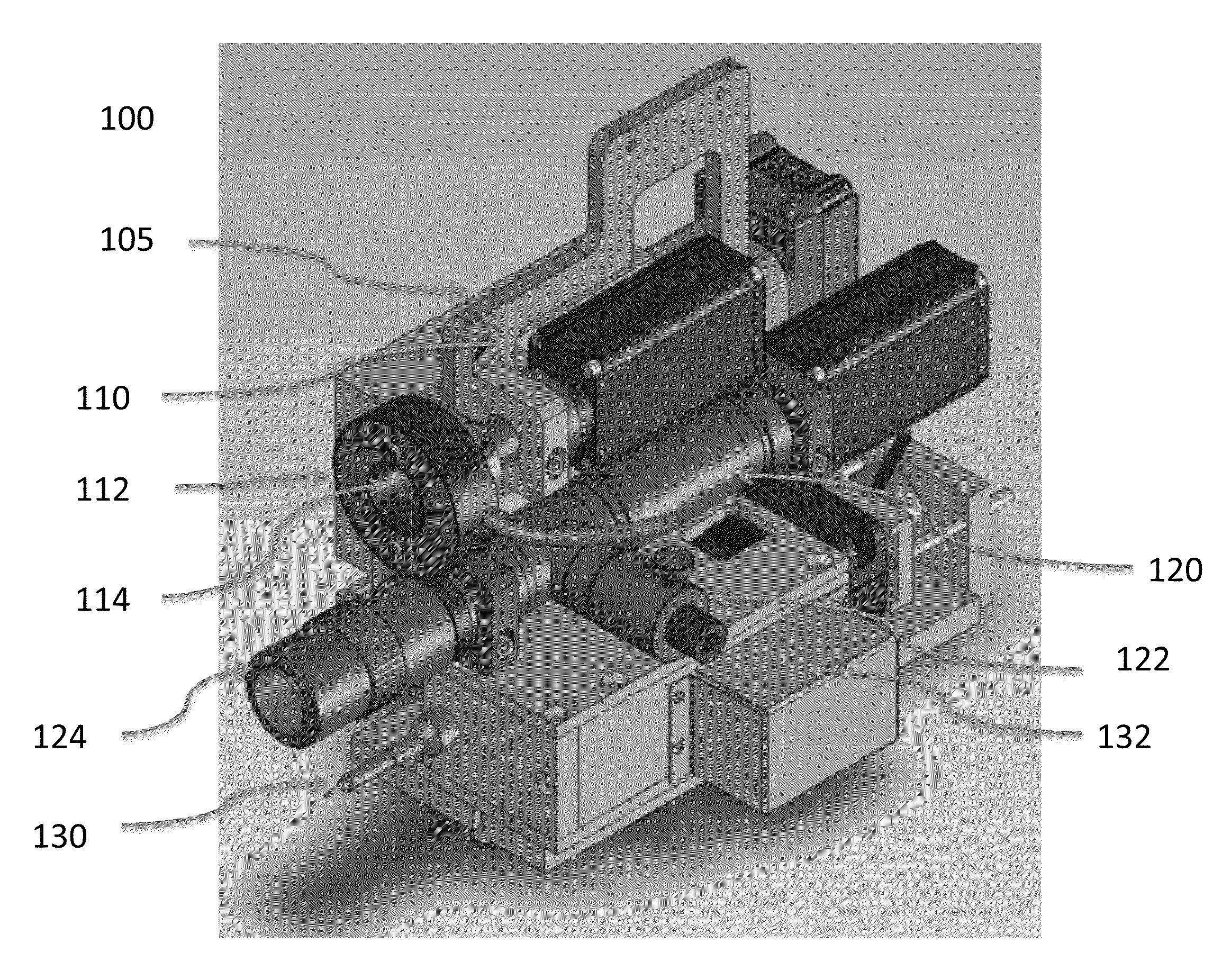
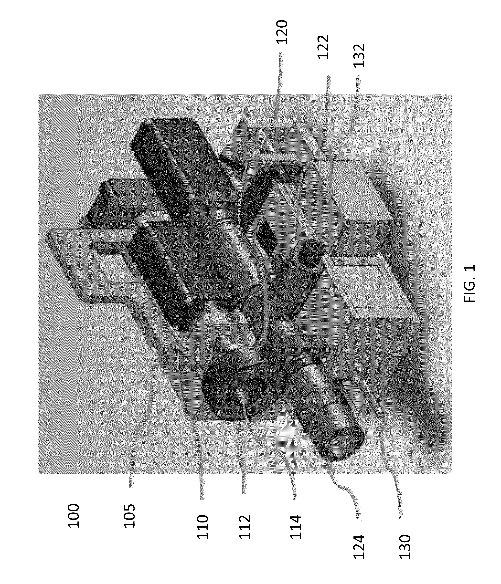
[0056]The invention provides methods and systems related to enhanced fiber optic end face cleaning and inspection. To obtain high levels of transmission in fiber optic systems such as are found in communication systems and various types of fiber optic sensors, it is important that the ends of the fiber optic connections be clean and defect free when installed. Consequently, it is important to be able to clean the ends of fiber optic components including the optical fibers and to be able to inspect the ends following cleaning to verify that the ends of the fiber optics are free of defects. The invention provides an automated system and methods for rapidly and efficiently cleaning and inspecting various types of fiber optic component. The system enables automatically locating, imaging, inspecting and cleaning the surfaces of fiber ends.

[0057]FIG. 1 is an illustration of a modular cleaning and inspection head assembly 100 in an embodiment of the invention. The head assembly 100 include...


PUM


Abstract

This disclosure concerns a cleaning and inspection system for fiber optics that is rapid, reliable and useful for various types of fiber optics. In an embodiment, the system includes a wide field of view (FOV) camera to image the ferrule and rapidly locate the fiber ends and a narrow FOV camera to provide detailed inspection of fiber ends. A cleaning module with a cleaning tip and a cleaning media that is drawn through the tip is used to clean the fiber ends. Images captured by the dual cameras are automatically enhanced and analyzed to determine the effectiveness of the cleaning process and to identify the types and quantity of defects present. In another embodiment, a single higher resolution camera is provided with a lens that can image an entire fiber array and yet enable defects to be detected by analysis of sub-images of each fiber in the fiber array.

Description

CROSS-REFERENCE TO RELATED APPLICATIONS[0001]This application claims the benefit of the following provisional application, which is hereby incorporated by reference in its entirety: U.S. Provisional Application 61 / 606,944, filed Mar. 5, 2012.[0002]This application is also related to the following U.S. patent, each of which is incorporated by reference herein in its entirety: U.S. Pat. No. 6,758,605.BACKGROUND[0003]1. Field[0004]The methods and systems described herein generally relate to enhanced fiber optic cleaning and inspection methods and systems.[0005]2. Description of the Related Art[0006]In fiber optic systems, it is important to provide very low losses of light at junctions between fibers and other optical devices, while retaining the flexibility of field interconnections. As a result, the end faces of fiber optic connectors must be smoothly polished to reduce scratches that scatter light and cleaned to remove contaminants and particles that block or scatter light. To verif...

Claims


Application Information

Patent Timeline
Patent Type & Authority Applications(United States)
IPC IPC(8): G01M11/00
CPCB08B1/00G01M11/31G02B6/3866G02B6/385G01M11/3145B08B11/00G01B11/30G01N21/88G01N21/94G01N2021/9511
Inventor WILSON, DOUGLAS H.ENDRESEN, JAN R.
Owner FIBERQA
Why Eureka
Try Eureka