This helps you quickly interpret patents by identifying the three key elements:
Problems solved by technology
Method used
Benefits of technology
Benefits of technology
The present invention provides a treatment apparatus for evaporated fuel with improved bleed emission performance by suppressing temperature drop in activated carbon. This is achieved by designing an adsorption chamber with a major diameter portion filled with adsorbent, a projecting portion that cools the air through desorption of fuel components from the adsorbent, and a space portion between the projecting portion and the inner wall of the channel that is not filled with adsorbent. This design allows for higher efficiency of desorption from the adsorbent and suppresses deterioration in adsorbent efficiency compared to conventional technologies, resulting in reduced residual fuel in the adsorption chamber and improved bleed emission performance.
Problems solved by technology
However, while desorption from activated carbon is promoted as the purge flow rate per time is increased, there is a problem that the activated carbon rapidly drops in temperature, efficiency of desorption from the activated carbon is reduced, a residual amount of the evaporated fuel in the activated carbon is increased, and a bleed emission performance is deteriorated.
As a result, a residual amount of the fuel component around the atmosphere port is increased, whereby the bleed emission performance is deteriorated.
Method used
Image
Click on the blue label to locate the original text in one second.
Reading with bidirectional positioning of images and text.
Examples
embodiment 1
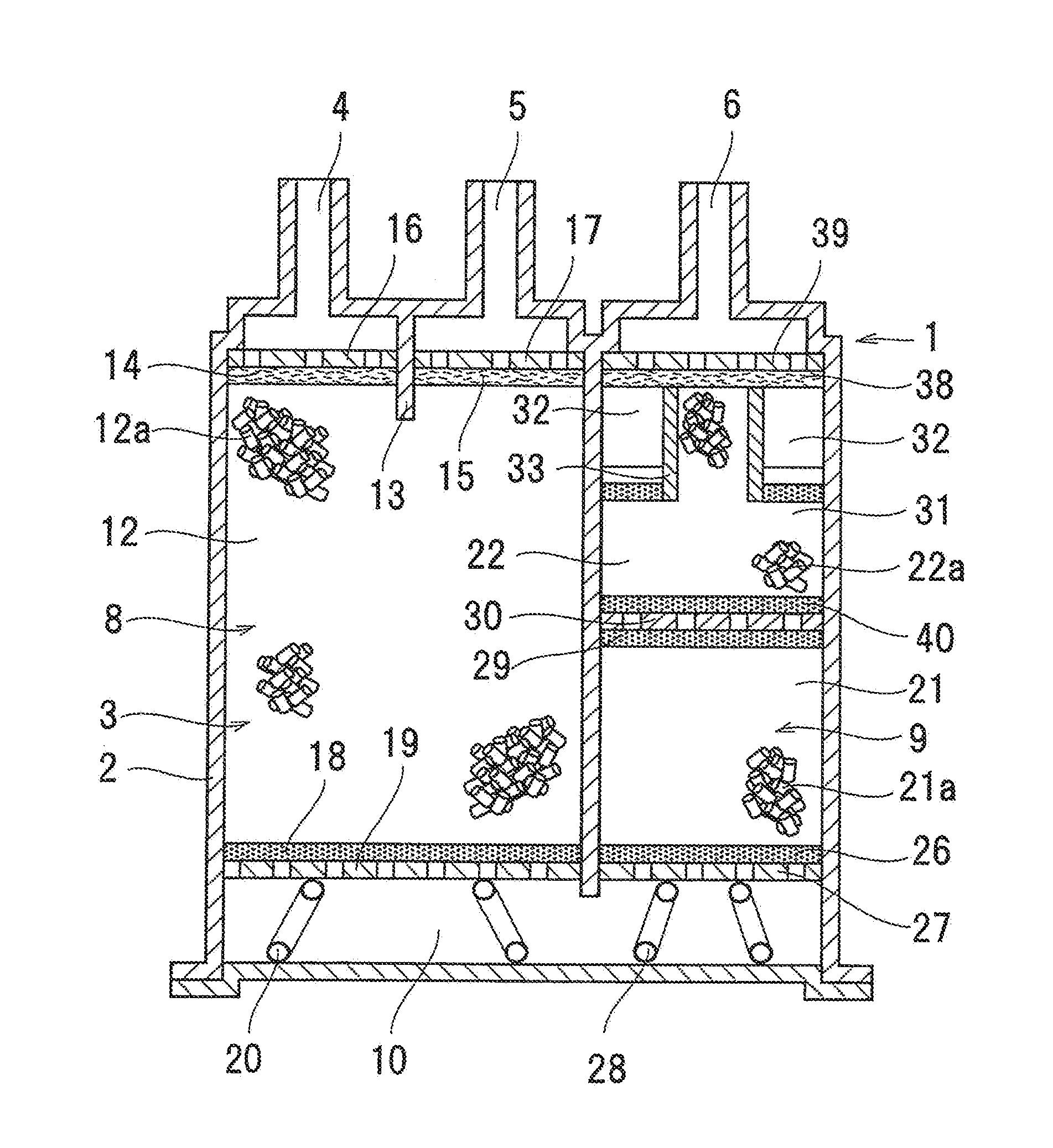
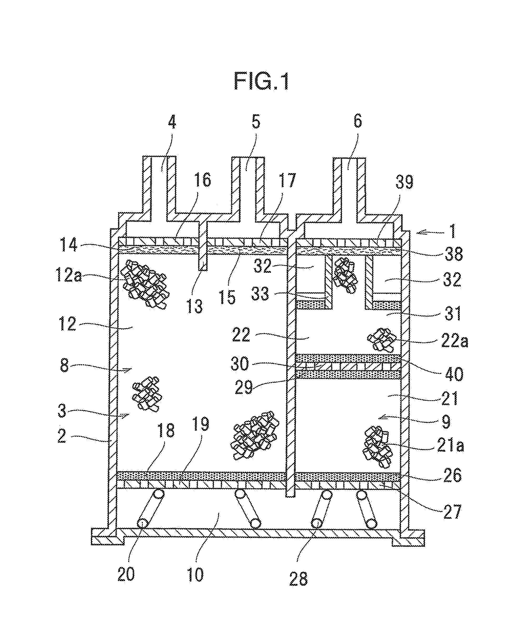
[0023]Embodiment 1 according to the present invention is shown in FIGS. 1 to 3B,
[0024]FIG. 1 is a schematic cross sectional view showing a treatment apparatus for evaporated fuel 1 according to Embodiment 1. The treatment apparatus for evaporated fuel 1 has a case 2, in which a channel 3 is formed so that fluid such as gas can pass therethrough. As shown in FIG. 1, a tank port 4 and a purge port 5 are formed in one end portion of the channel 3 in the case 2, while an atmosphere port 6 is formed in the other end portion thereof.
[0025]In the case 2, a main chamber 8 that is communicated with the tank port 4 and with the purge port 5, and an sub chamber 9 that is commnunicated with the atmosphere port 6 are formed. As shown in FIG. 1, the main chamber 8 and the sub chamber 9 are comparted, and they are communicated with each other through a space 10 which is formed on the opposite side of the atmosphere port 6 in the case 2. When gas flows into the atmosphere port 6 from the tank port ...
embodiment 2
[0044]In Embodiment 1, the central axis of the partition wall 33a, i.e. the axial center of the projecting portion 31b in the channel 3 direction, is formed generally concentric with the axial center of the atmosphere port 6 in the vicinity of the treatment apparatus for evaporated fuel 1. However, as shown in FIG. 4, for example, the axial center of the projecting portion 31b in the channel 3 direction may be formed non concentric with the axial corner of the atmosphere port 6 in the vicinity of the treatment apparatus for evaporated fuel 1.
[0045]Since other configuration aspects are similar to those in Embodiment 1, the description thereof will be omitted.
[0046]In Embodiment 2, the same effects as those in Embodiment 1 can also be implemented.
embodiment 3
[0047]In Embodiment 3, for example, as shown in FIG. 5, a second projecting portion 41 is provided which projects from the major diameter portion 31a of Embodiment 1 or 2 toward the second adsorption chamber 21. The second projecting portion 41, the major diameter portion 31a, and the projecting portion 31b are integrally formed with one another. A second space portion 42 is provided between an outer peripheral portion of the second projecting portion 41 and the inner wall 3a of the channel 3, and a partition wall 43 is formed between the second projecting portion 41 and the second space portion 42. The partition wall 43 prevents fluid from directly flowing between the second space portion 42 and the second projecting portion 41.
[0048]Although it is preferable to provide the partition wall 43 to prevent the fluid from directly flowing between the second space portion 42 and the second projecting portion 41, it is also possible to allow air bow between the second space portion 42 and...
PUM
Abstract
A treatment apparatus for evaporated fuel including tank port, a purge port, an atmosphere port, a channel communicating the tank port or the purge port and the atmosphere port, and plural adsorption chambers having adsorbent therein, which adsorbing and desorbing a fuel component of evaporated fuel, wherein the adsorption chamber closest to the atmosphere port has a major diameter portion filled with the adsorbent over all a cross section of the charmed a projecting portion projecting from the major diameter portion toward the atmosphere port and filled with the adsorbent, and a space portion between the projecting portion and an inner wall of the channel and not filled with the adsorbent, and end surfaces of the major diameter portion and the projecting portion on the atmosphere port side are breathable so as to control temperature drop in activated carbon and to thereby enhance bleed emission performance.
Description
BACKGROUND OF THE INVENTION[0001](1) Field of the Invention[0002]The preset invention relates to a treatment apparatus for evaporated fuel.[0003](2) Description of Related Art[0004]In order to prevent evaporated, fuel from being released to the atmosphere from an automobile fuel task or the like, a treatment apparatus for evaporated fuel (hereinafter also referred to as a canister) is conventionally used which temporarily adsorbs a fuel component in the evaporated fuel.[0005]In recent years, it is desired in the canister to reduce an amount of evaporated fuel released to the atmosphere. Accordingly, it is known that an adsorption chamber which is positioned closest to an atmosphere port and is fitted with activated carbon is made to have a smaller cross section toward the atmosphere port, so that the adsorption chamber close to the atmosphere port is to have a larger ratio of length to cross sectional diameter (L / D) in order to decrease the amount of bleed emissions to the atmospher...
Claims
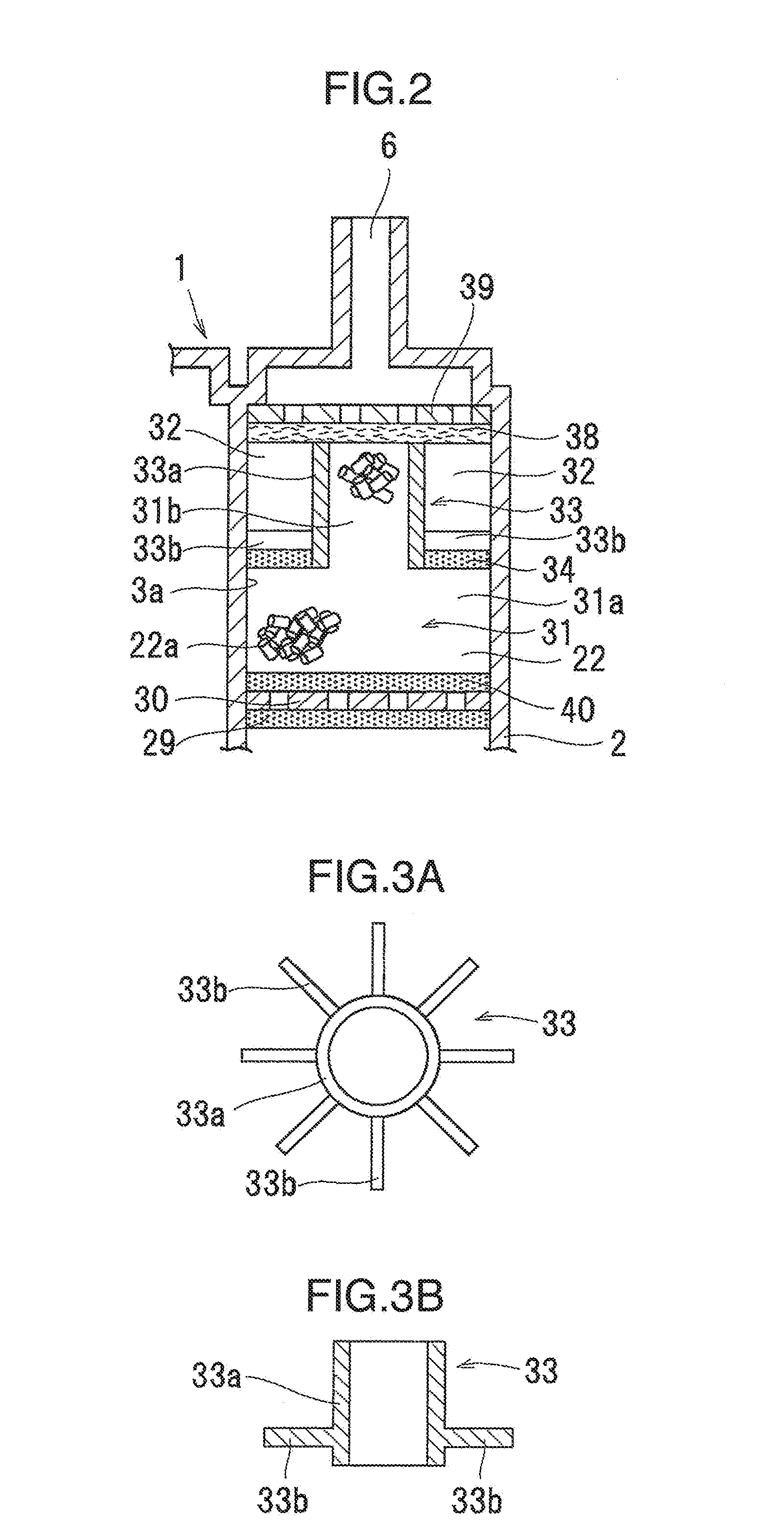
Application Information
Patent Timeline
Application Date:The date an application was filed.
Publication Date:The date a patent or application was officially published.
First Publication Date:The earliest publication date of a patent with the same application number.
Issue Date:Publication date of the patent grant document.
PCT Entry Date:The Entry date of PCT National Phase.
Estimated Expiry Date:The statutory expiry date of a patent right according to the Patent Law, and it is the longest term of protection that the patent right can achieve without the termination of the patent right due to other reasons(Term extension factor has been taken into account ).
Invalid Date:Actual expiry date is based on effective date or publication date of legal transaction data of invalid patent.

