Supercharge Your Innovation With Domain-Expert AI Agents!

Coolant circuit for internal combustion engine with inlet-side flow control

a technology of internal combustion engine and cooling circuit, which is applied in the direction of engine cooling apparatus, liquid cooling, machines/engines, etc., can solve the problems of increasing control cost, space requirement, and weight, reducing the temperature of the coolant, reducing the number of components, and reducing the cost of procurement and assembly

Inactive Publication Date: 2013-07-25
FORD GLOBAL TECH LLC
View PDF14 Cites 25 Cited by
  • Summary
  • Abstract
  • Description
  • Claims
  • Application Information

AI Technical Summary

Benefits of technology

The patent describes a control system for an internal combustion engine that reduces costs and space requirements. It achieves this by using a single setting element instead of two thermostat valves. This results in a reduction of components and assembly costs. The control system also includes a fan that is connected to the heat exchanger to improve air flow and aid in heat transfer. This fan can be controlled in a continuous manner to adjust its speed and load. Overall, this control system reduces costs and weight, and provides better performance and efficiency for the engine.

Problems solved by technology

A disadvantage of the control as per U.S. Pat. No. 6,595,164 is that two shut-off elements, that is to say two thermostat valves, are required.
This increases the costs of the control, the space requirement and the weight.
A further disadvantage of the described control is that the circulation of the coolant in the cooling circuit, that is to say the flow of coolant, cannot be prevented in a targeted manner, not even after a cold start of the internal combustion engine.
A self-controlling thermostat valve with an invariant, component-specific operating temperature must be suitable for all load states and therefore have an opening temperature configured for high loads, which is comparatively low and leads to relatively low coolant temperatures even in part-load operation.

Method used


Image

  • Coolant circuit for internal combustion engine with inlet-side flow control
  • Coolant circuit for internal combustion engine with inlet-side flow control

Examples


Embodiment Construction

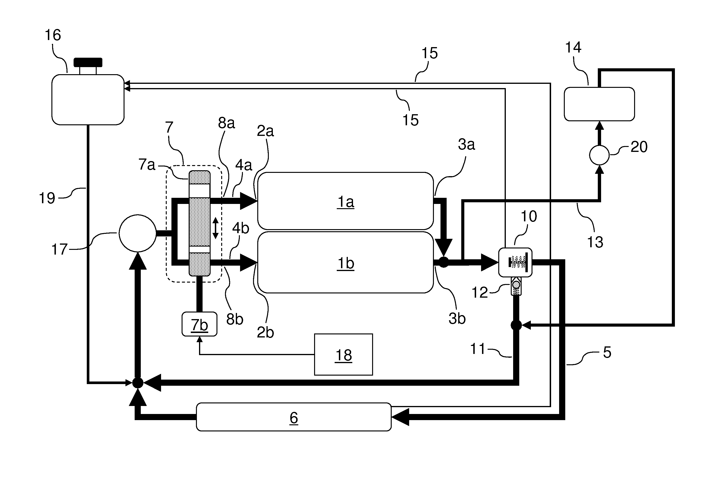
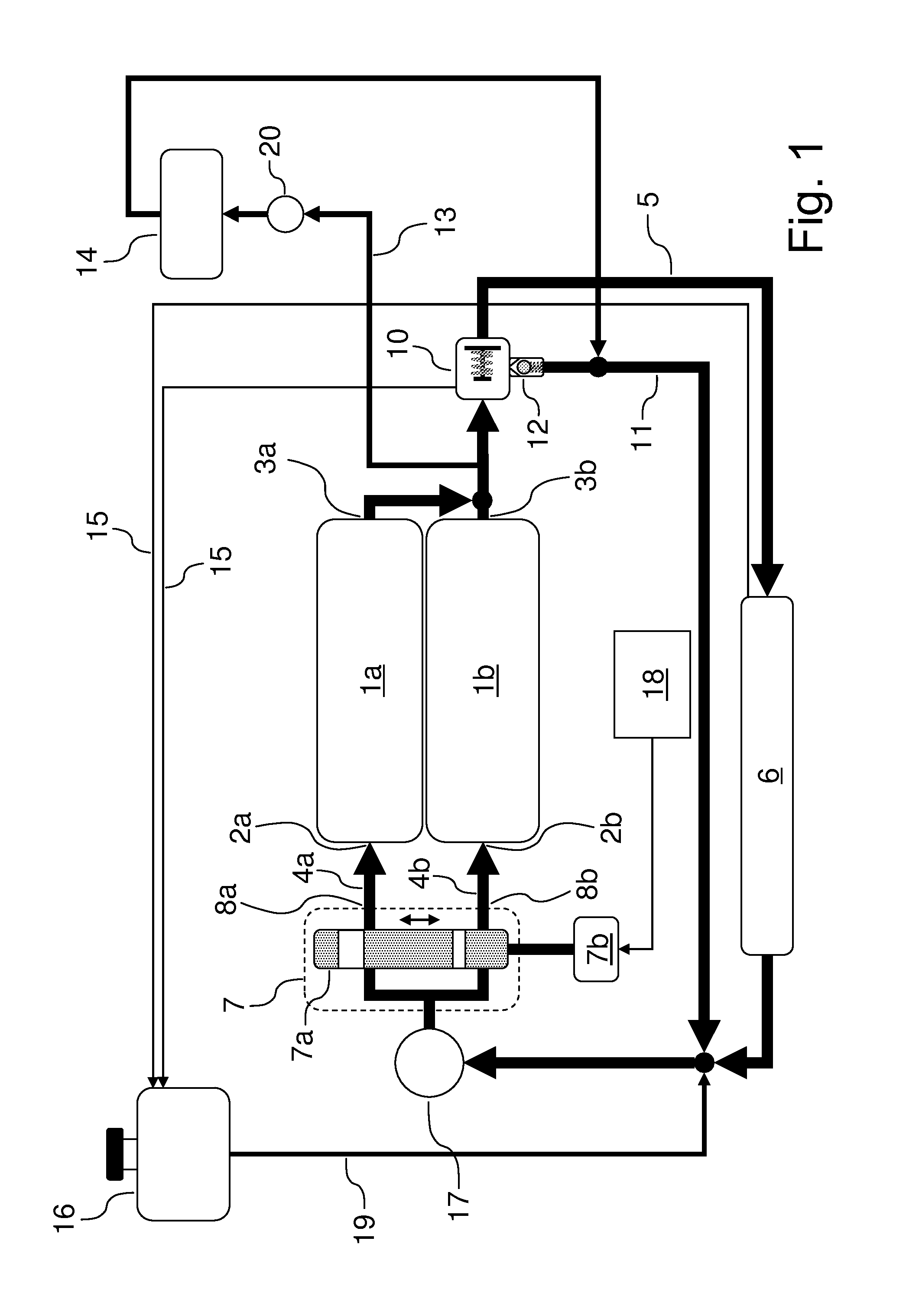
[0075]FIG. 1 schematically shows a first embodiment of the internal combustion engine 1 having a cylinder head 1a and a cylinder block 1b. The internal combustion engine 1 is equipped with a liquid-type cooling arrangement, wherein the cylinder head 1a has a first integrated coolant jacket which has a first supply opening 2a at the inlet side for the feed of coolant and has a first discharge opening 3a at the outlet side for the discharge of the coolant. The cylinder block 1b likewise has an integrated coolant jacket. Said second coolant jacket has a second supply opening 2b at the inlet side for the feed of coolant and has a second discharge opening 3b at the outlet side for the discharge of the coolant.

[0076]To form a coolant circuit, the outlet-side discharge openings 3a, 3b can be connected to the inlet-side supply openings 2a, 2b via a recirculation line 5, wherein a heat exchanger 6 (such as a radiator) is arranged in the recirculation line 5. A pump 17 for delivering the cool...


PUM


Abstract

An internal combustion engine cylinder head has a coolant jacket with a first supply opening and a first discharge opening. A cylinder block coolant jacket has a second supply opening and a second discharge opening. A coolant circuit connects the discharge openings to the supply openings via a recirculation line and a heat exchanger. A control unit has an inlet connected to a pump outlet, a first outlet connected to the first supply opening, a second outlet connected to the second supply opening, and a single setting element. The setting element has a first working position that opens up the first outlet and blocks the second outlet such that the coolant circuit is activated through the cylinder head and is deactivated through the cylinder block. The setting element has a second working position that opens up both the first outlet and the second outlet.

Description

CROSS REFERENCE TO RELATED APPLICATIONS[0001]This application claims priority to application 102012200746.6, filed in the German Patent and Trademark Office on Jan. 19, 2012, which is hereby incorporated by reference.STATEMENT REGARDING FEDERALLY SPONSORED RESEARCH[0002]Not Applicable.BACKGROUND OF THE INVENTION[0003]The present invention relates in general to cooling of internal combustion engines, and, more specifically, to a coolant circuit with flow into the engine being diverted between the cylinder head and the cylinder block according to the operating conditions of the engine.[0004]The invention is an improvement to a liquid-cooled internal combustion engine having at least one cylinder head and one cylinder block, in which[0005]the at least one cylinder head is equipped with at least one integrated coolant jacket, said first coolant jacket having, at the inlet side, a first supply opening for the feed of coolant and, at the outlet side, a first discharge opening for the disc...

Claims


Application Information

Patent Timeline
IPC IPC(8): F01P5/10
CPCF01P5/10F01P2003/027F01P7/165F01P3/02F01P7/16
Inventor QUIX, HANS GUENTERMEHRING, JAN
Owner FORD GLOBAL TECH LLC
Features
  • R&D
  • Intellectual Property
  • Life Sciences
  • Materials
  • Tech Scout
  • Unparalleled Data Quality
  • Higher Quality Content
  • 60% Fewer Hallucinations
Learn More