X-ray tube window cooling apparatus

a technology for cooling apparatus and x-ray tubes, which is applied in the direction of x-ray tubes, x-ray tube details, nuclear engineering, etc., can solve the problems of reducing the performance of cooling fluid, reducing the efficiency of cooling fluid, and new constraints and requirements for the functionality of ct imaging systems. the effect of cooling fluid temperatur

Inactive Publication Date: 2006-03-21
GENERAL ELECTRIC CO
View PDF6 Cites 13 Cited by
  • Summary
  • Abstract
  • Description
  • Claims
  • Application Information

AI Technical Summary

Benefits of technology

[0012]The present invention provides an x-ray tube window cooling assembly for an x-ray tube that includes an electron collector body. The electron collector body is thermally coupled to an x-ray tube window. The electron collector body includes a coolant circuit with a coolant inlet and a coolant outlet. Multiple thermal exchange devices are coupled to the coolant circuit and reduce temperature of a coolant passing through the exchange devices.

Problems solved by technology

Although the increase in imaging speed provides improved imaging capability, the increase causes new constraints and requirements for the functionality of the CT imaging systems.
The high voltage potential produces a large amount of heat within the x-ray tube, especially within the anode.
High temperatures at an interface between the vacuum vessel and a transmissive window in the casing cause the cooling fluid to boil, which may degrade the performance of the cooling fluid.
Bubbles may form within the fluid and cause high voltage arcing across the fluid.
The arcing degrades the insulating ability of the fluid.
The bubbles can cause image artifacts that can result in low quality images.
Due to the inherent poor efficiency of x-ray production and the desire for increased x-ray flux, heat load is increased that must be dissipated.
Approximately 40% of the electrons within the electron beam are back-scattered from the anode and impinge on other components within the vacuum vessel, causing additional heating of the x-ray tube.
As a result, the x-ray tube components are subjected to high thermal stresses that decrease component life and reliability of the x-ray tube.
These approaches, however, do not provide for significant levels of energy storage a dissipation.
Bubbles generated from the boiling coolant can obscure the window and thereby compromise image quality.
Extensive boiling of the coolant results in chemical breakdown of the coolant and the formation of sludge on the window, which also results in poor image quality.

Method used


Image

  • X-ray tube window cooling apparatus
  • X-ray tube window cooling apparatus
  • X-ray tube window cooling apparatus

Examples


Embodiment Construction

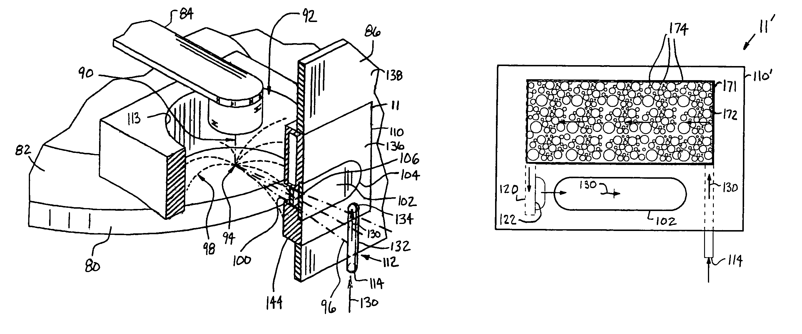
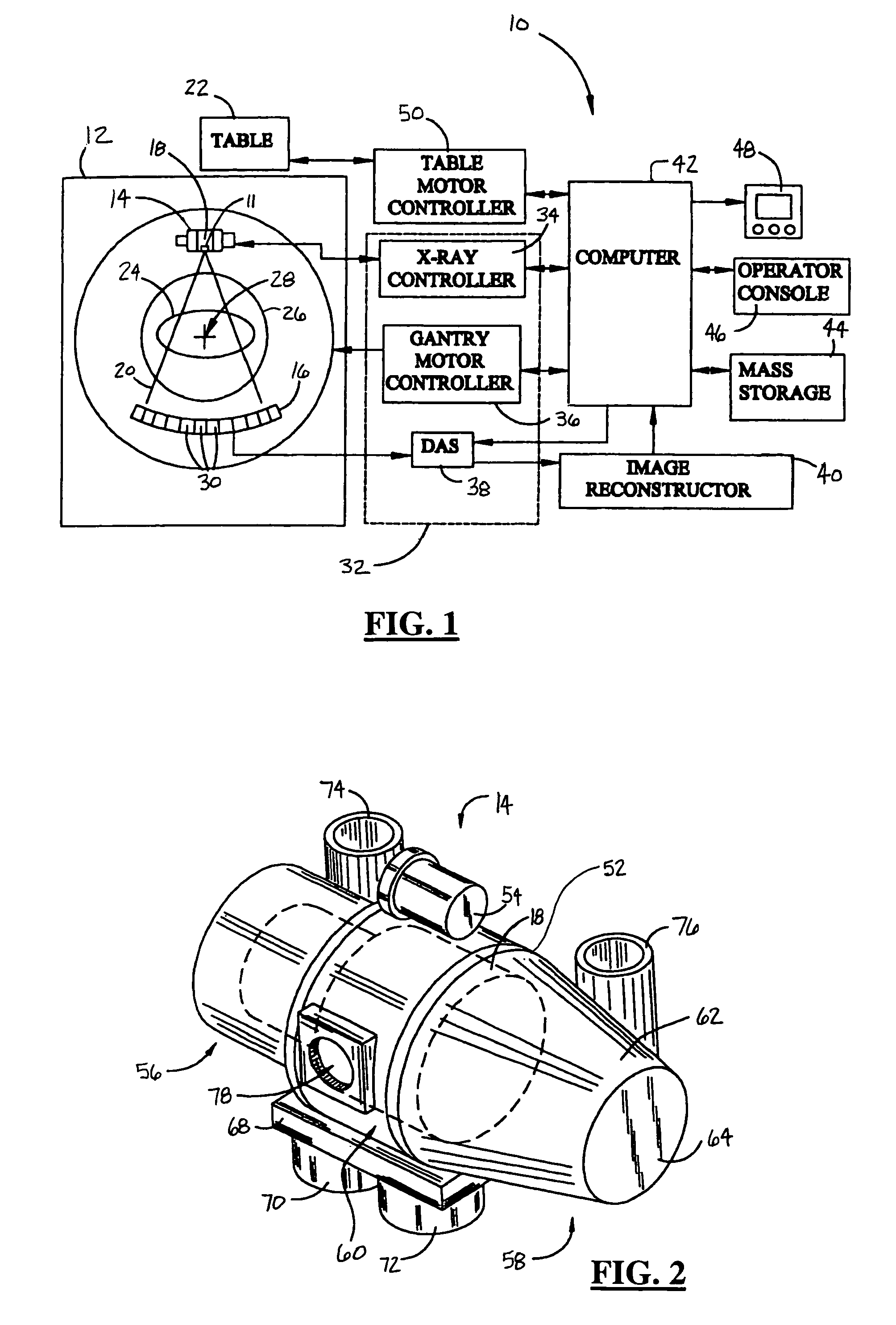
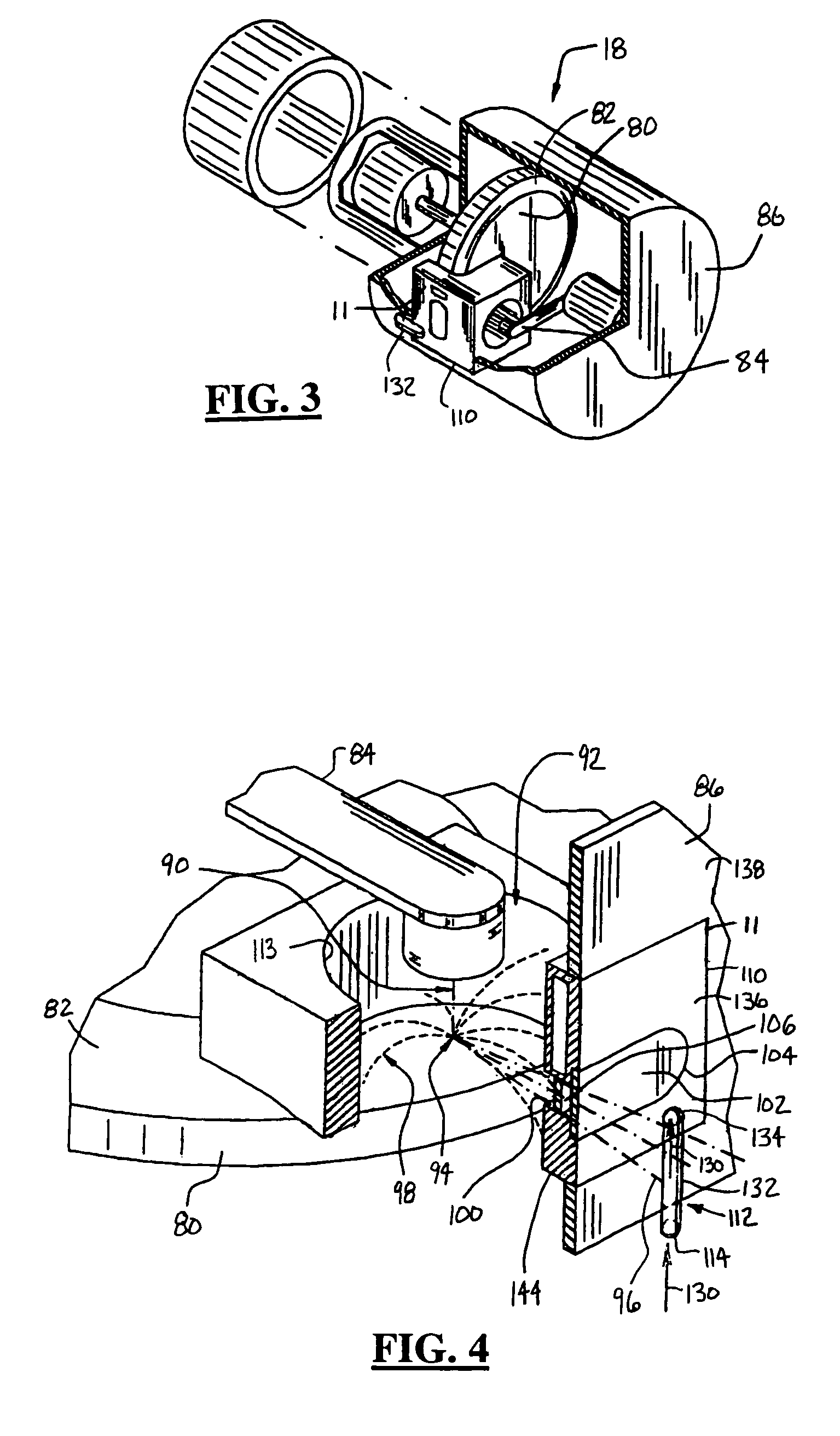
[0026]While the present invention is described with respect to an assembly for cooling an x-ray tube window within a computed tomography (CT) imaging system, the following apparatus and method is capable of being adapted for various purposes and is not limited to the following applications: MRI systems, CT systems, radiotherapy systems, flouroscopy systems, X-ray imaging systems, ultra sound systems, vascular imaging systems, nuclear imaging systems, magnetic resonance spectroscopy systems, and other applications known in the art.

[0027]In the following description, various operating parameters and components are described for one constructed embodiment. These specific parameters and components are included as examples and are not meant to be limiting.

[0028]Also, in the following description the term “impinge” refers to an object colliding directly with another object. For example, as known in the art, an electron beam impinges upon a target of an anode within an x-ray tube. The elec...


PUM


Abstract

An x-ray tube window cooling assembly (11) for an x-ray tube (18) includes an electron collector body (110). The electron collector body (110) is thermally coupled to an x-ray tube window (102). The electron collector body (110) includes a coolant circuit (112) with a coolant inlet (114) and a coolant outlet (122). Multiple thermal exchange devices are coupled to the coolant circuit (112) and reduce temperature of a coolant passing through the exchange devices.

Description

RELATED APPLICATION[0001]The present application is a Continuation-In-Part (CIP) application of U.S. patent application Ser. No. 10 / 065,392, filed Oct. 11, 2002, now U.S. Pat. No. 6,714,626 entitled “JET COOLED X-RAY TUBE WINDOW”, which is incorporated by reference herein.TECHNICAL FIELD[0002]The present invention relates generally to thermal energy management systems within electron beam generating devices. More particularly, the present invention relates to an assembly for cooling an x-ray tube window.BACKGROUND OF THE INVENTION[0003]There is a continuous effort to increase scanning capabilities of x-ray imaging systems. This is especially true in computed tomography (CT) imaging systems. Customers desire the ability to perform longer scans at increased power levels. The increase in scan times at higher power levels allows physicians to gather CT images and constructions in a matter of seconds rather than in a matter of several minutes as with previous CT imaging systems. Although...

Claims


Application Information

Patent Timeline
Patent Type & Authority Patents(United States)
IPC IPC(8): H01J35/16G21K5/02G21K5/00H01J19/74H01J35/00H01J35/10H01J35/12H01J35/18H05G1/02
CPCH01J35/18H05G1/025H05G1/02H01J2235/122H01J2235/1283
Inventor SUBRAYA, MADHUSUDHANA T.ROGERS, CAREY S.KOLLEGAL, MANOHAR G.SNYDER, DOUGTRUSZKOWSKA, KRYSTYNA
Owner GENERAL ELECTRIC CO
Why Eureka
Try Eureka