Starting of an internal combustine engine

Active Publication Date: 2013-07-25
WARTSILA FINLAND OY
View PDF4 Cites 1 Cited by
  • Summary
  • Abstract
  • Description
  • Claims
  • Application Information

AI Technical Summary

Benefits of technology

[0020]With the method according to the present invention, the starting air consump

Problems solved by technology

Pressurized starting air needs to be stored in large air receivers that require a lot of space.
This means that the crank angle cannot be determined when the engine is at rest.
A drawback of this method is that the method is time consuming and a lot of energy is ne

Method used


Image

  • Starting of an internal combustine engine
  • Starting of an internal combustine engine
  • Starting of an internal combustine engine

Examples


Embodiment Construction

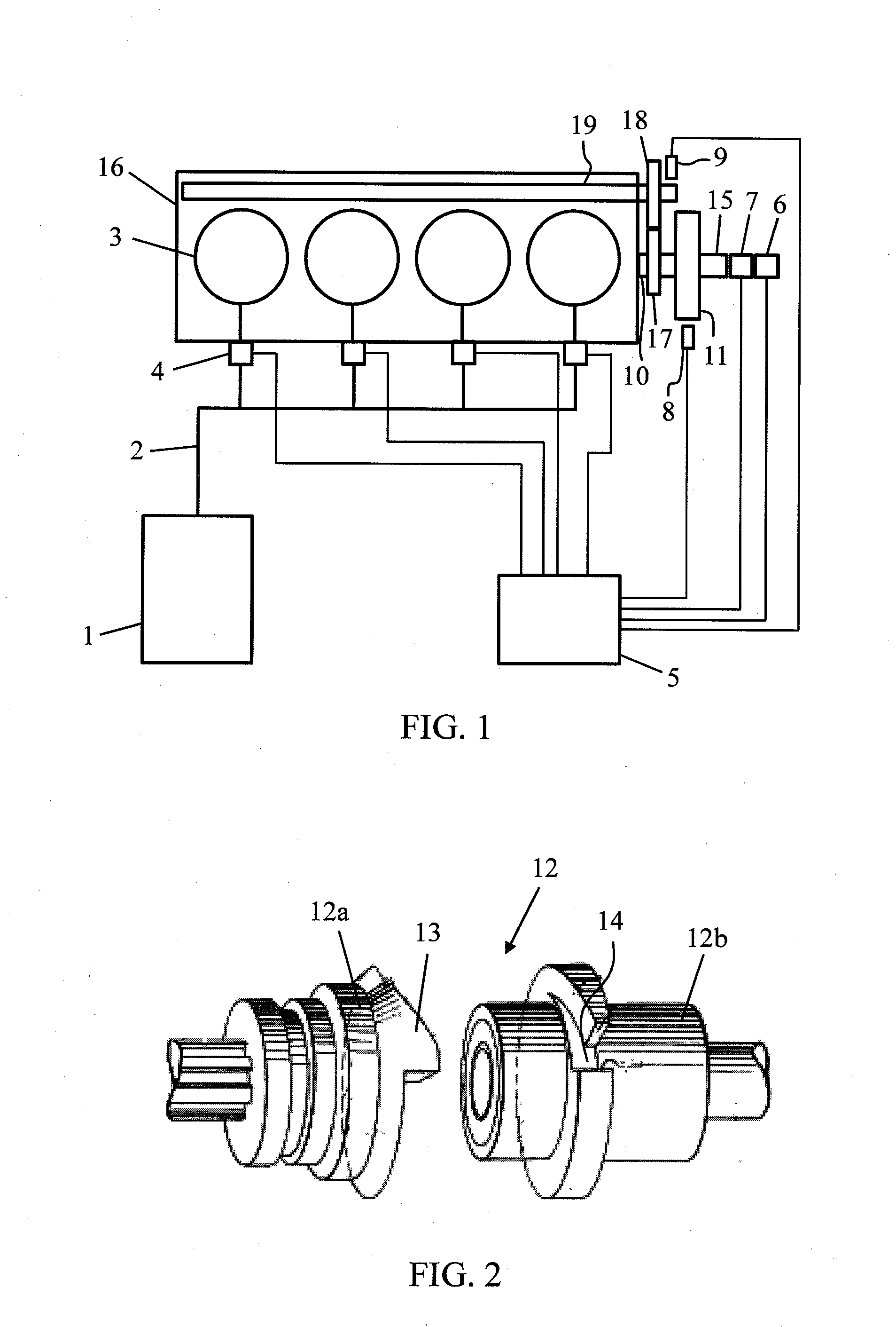
[0026]The invention is now described in more detail with reference to the accompanying drawings. FIG. 1 shows schematically a simplified illustration of a starting system according to the present invention. The starting system comprises an air receiver 1 for storing pressurized air that can be used for starting an engine 16. The system also comprises a pipe system 2 for introducing the starting air into the cylinders 3 of the engine 16. The engine 16 is a large internal combustion engine that could be used for instance in a power plant or as a main or auxiliary engine of a ship. In FIG. 1 is shown an embodiment with four cylinders 3, but the engine 16 can comprise any reasonable number of cylinders 3 arranged for instance in-line or in a V-configuration. A starting valve 4 is arranged in connection with each cylinder 3 for controlling the admission of starting air into the cylinder 3. The operation of the starting valves 4 is controlled by a control unit 5. The starting valves 4 can...


PUM


Abstract

A starting system for an internal combustion engine comprising a pressure medium source, means for connecting the pressure medium source to at least two of the cylinders of the engine, a starting valve in connection with each cylinder that is connected to the pressure medium source for controlling the admission of the pressure medium into the cylinder, a control unit for controlling the operation of the starting valves, and an absolute rotary encoder for determining the crank angle of the engine. The system further comprises coupling means arranged between the engine and the absolute rotary encoder for releasably coupling the encoder to the engine. The invention also concerns a method for starting an internal combustion engine and an internal combustion engine.

Description

TECHNICAL FIELD OF THE INVENTION[0001]The present invention relates to a starting system for an internal combustion engine in accordance with the preamble of claim 1. The invention also concerns a method for starting an internal combustion engine and an internal combustion engine, as defined in the preambles of other independent claims.BACKGROUND OF THE INVENTION[0002]Large internal combustion engines that are used for instance in ships and power plants are usually started by using pressurized air that is injected sequentially into the cylinders of the engine for rotating the crankshaft. It is desirable to minimize the amount of starting air that is needed for starting an engine. Pressurized starting air needs to be stored in large air receivers that require a lot of space. The energy needed for pressurizing the starting air is usually taken from the engine itself, and it is therefore also desirable to minimize the energy consumption for this purpose.[0003]To minimize the consumptio...

Claims


Application Information

Patent Timeline
IPC IPC(8): F02N19/00
CPCF02N9/04F02N15/022F02B21/00F02N2200/021F02N19/00F02N15/028
Inventor BJORKLUND, DANMANTYLA, JUKKA
Owner WARTSILA FINLAND OY
Why Eureka
Try Eureka