Article with curved patterns formed of aligned pigment flakes

a technology of aligned pigment flakes and curved patterns, which is applied in the direction of magnetic materials, inks, magnetic bodies, etc., can solve the problem that the optically variable devices intended to be noticed are not widely known

Active Publication Date: 2013-07-25
VIAVI SOLUTIONS INC
View PDF1 Cites 21 Cited by
  • Summary
  • Abstract
  • Description
  • Claims
  • Application Information

AI Technical Summary

Benefits of technology

[0008]An article includes a substrate and a coating which contains pigment flakes in a binder and is supported by the substrate. Each of the pigment flakes includes a magnetic or magnetizable material for magnetic alignment of the pigment flakes, and the pigment flakes are aligned so as to form an aligned pattern wherein a portion of the pigment flakes have their substantially planar major surfaces parallel to the substrate along a continuous imaginary line on a surface of the substrate between first and second points thereof, and the pigment flakes form curved patterns in a plurality of cross-sections normal the continuous imaginary line so that radii of the curved patterns increase along the imaginary line from the first point to the second point. When light is incident upon the pigment flakes from a light source, light reflected from the aligned pattern forms a bright image which appears to gradually change its shape and move from one side of the continuous imaginary line to another side of the continuous imaginary line when the substrate is tilted with respect to the light source.

Problems solved by technology

Unfortunately, some optically variable devices that are intended to be noticed are not widely known because the optically variable aspect of the device is not sufficiently dramatic.

Method used


Image

  • Article with curved patterns formed of aligned pigment flakes
  • Article with curved patterns formed of aligned pigment flakes
  • Article with curved patterns formed of aligned pigment flakes

Examples


Embodiment Construction

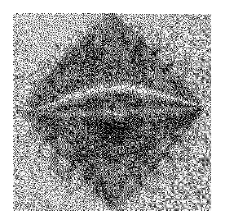
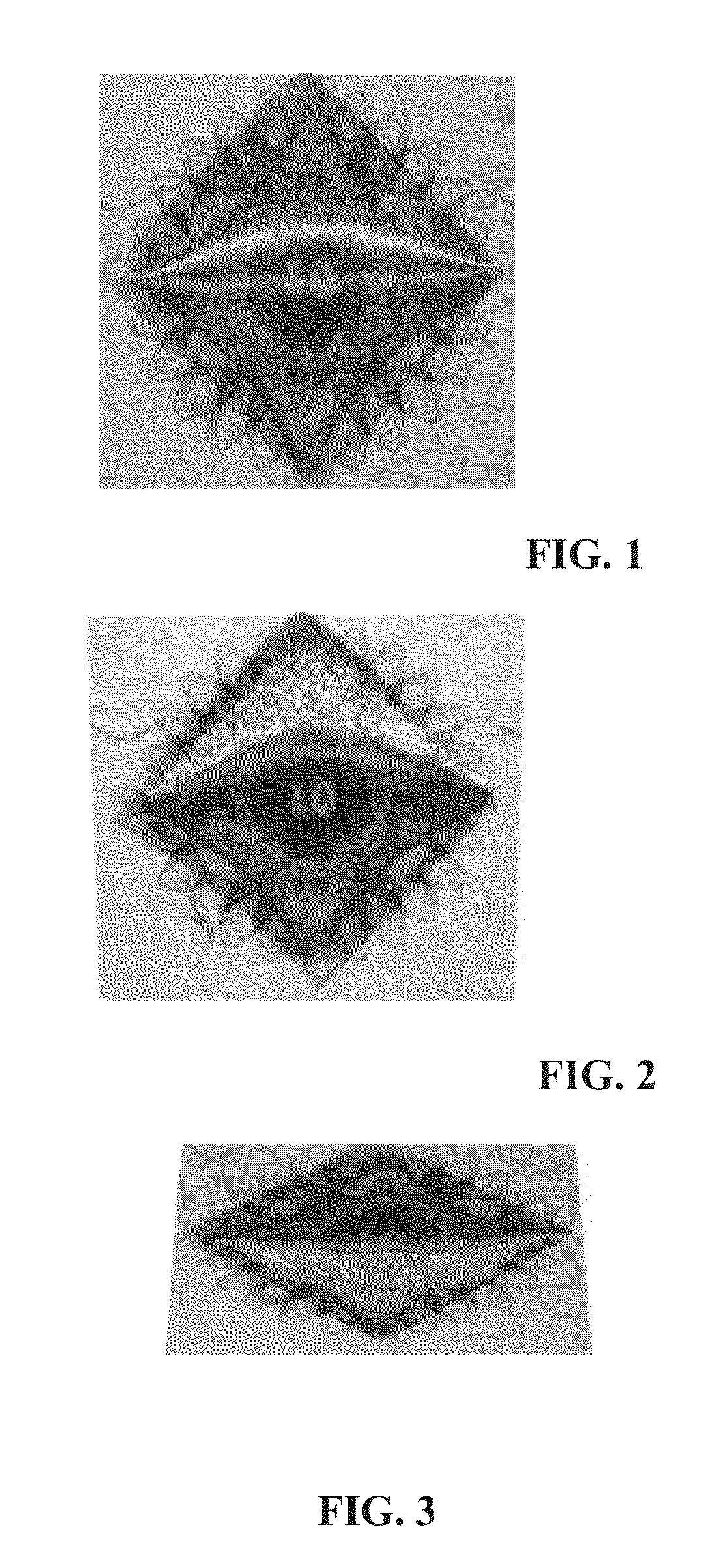
[0054]A previously unknown effect has been discovered by the inventors in their search for new printed devices which would provide highly noticeable dynamic optical effects. It has been found that a square magnet magnetized through its diagonal may align magnetically alignable pigment flakes to produce a “boomerang” optical effect visible to a naked human eye and illustrated in FIGS. 1-3.

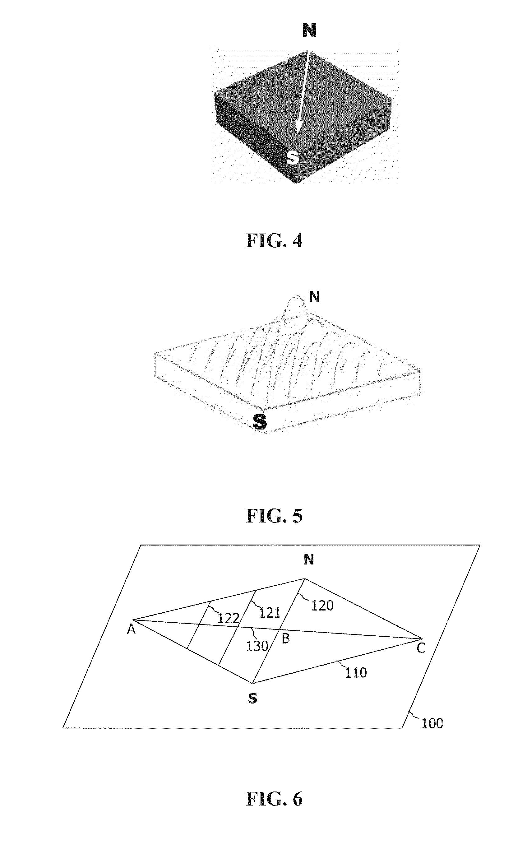
[0055]With reference to FIG. 4, a square magnet is magnetized through its diagonal; force lines of the magnetic field are illustrated in FIG. 5. The radii of the force lines change across the magnet. Consequently, the radii of the alignment formed of pigment flakes also change, which results in a dynamic image simultaneously moving and gradually changing its shape.

[0056]When an ink or paint containing magnetically alignable flakes is applied to a surface of a substrate, and the flakes are aligned using the magnet shown in FIG. 4, the flakes form an aligned pattern which may be described with referen...


PUM

PropertyMeasurementUnit
anglesaaaaaaaaaa
widthaaaaaaaaaa
widthaaaaaaaaaa

Abstract

In a printed article, pigment flakes are magnetically aligned so as to form curved patterns in a plurality of cross-sections normal a continuous imaginary line, wherein radii of the curved patterns increase along the imaginary line from the first point to the second point. When light is incident upon the aligned pigment flakes from a light source, light reflected from the aligned pattern forms a bright image which appears to gradually change its shape and move from one side of the continuous imaginary line to another side of the continuous imaginary line when the substrate is tilted with respect to the light source.

Description

CROSS-REFERENCE TO RELATED APPLICATIONS[0001]The present invention claims priority from U.S. Provisional Patent Application No. 61 / 585,954 filed Jan. 12, 2012, incorporated herein by reference.TECHNICAL FIELD[0002]The present invention relates generally to optically variable devices and, more particularly, to aligning or orienting magnetic flakes in a painting or printing process in order to obtain a dynamic optical effect.BACKGROUND OF THE INVENTION[0003]Optically variable devices are used in a wide variety of applications, both decorative and utilitarian; for example, such devices are used as security devices on commercial products. Optically variable devices can be made in numerous ways and achieve a variety of effects. Examples of optically variable devices include holograms imprinted on credit cards and authentic software documentation, color-shifting images printed on banknotes and enhancing the surface appearance of items such as motorcycle helmets and wheel covers.[0004]Opti...

Claims


Application Information

Patent Timeline
Patent Type & Authority Applications(United States)
IPC IPC(8): B44F1/10C09D7/61
CPCB41M7/0072C09D7/1216C09D11/00B42D2033/16B42D2033/20B42D2035/16B42D2035/20B44F1/10B05D3/207B05D5/061B44F1/02B42D25/29B42D25/00C09D5/29C09D5/36B41M3/14B42D25/369B42D25/378B42D25/41C09D7/61G02B5/08B41M1/00B42D25/342H01F41/0253
Inventor RAKSHA, VLADIMIR P.HYNES, JOHNHOLDEN, LAURENCECOOMBS, PAUL G.
Owner VIAVI SOLUTIONS INC
Why Eureka
Try Eureka