Vibration Robust X-Axis Ring Gyro Transducer

Active Publication Date: 2013-08-01
NXP USA INC
View PDF9 Cites 27 Cited by
  • Summary
  • Abstract
  • Description
  • Claims
  • Application Information

AI Technical Summary

Problems solved by technology

However, conventional MEMS gyroscopes have performance limitation

Method used


Image

  • Vibration Robust X-Axis Ring Gyro Transducer
  • Vibration Robust X-Axis Ring Gyro Transducer
  • Vibration Robust X-Axis Ring Gyro Transducer

Examples


Embodiment Construction

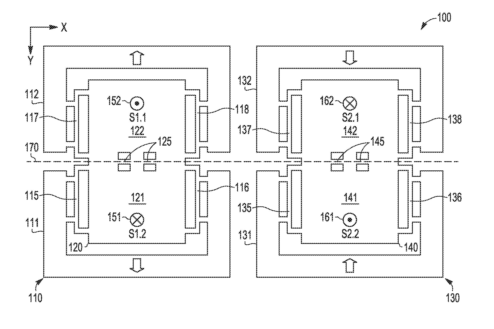
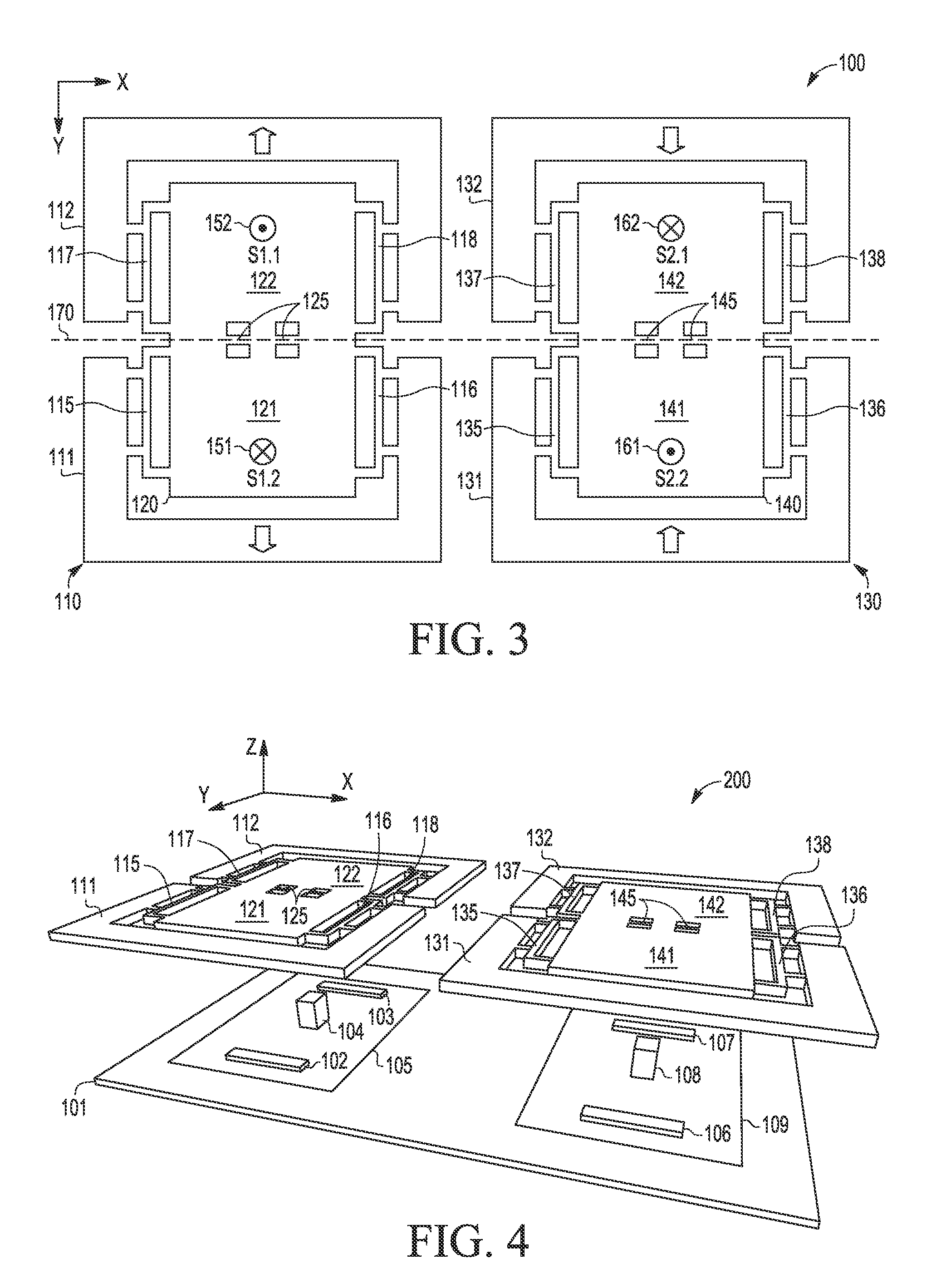
[0017]A lateral axis gyroscope sensor and associated methodology of operation are described wherein a pair of symmetric mass transducers is configured to vibrate synchronously in opposition to one another to cancel or reduce detected rotational acceleration or vibration forces, thereby providing vibration robust sensing. Depending on the shape of the vibrating mass transducers, the pair of symmetric mass transducers can measure rotational rate from the detected Coriolis forces while achieving compensation of the injected vibrational torque to make the sensor design robust against variations of the boundary conditions. In selected embodiments, the gyroscope sensor includes a pair of symmetrically designed and synchronized gyro structures, each including a sense element with opposed drive elements. With each gyro structure including a quadrilateral sense mass that is anchored to the substrate by a torsion spring and that is attached to a pair of opposing drive masses via linear spring...


PUM


Abstract

A micro-electromechanical systems (MEMS) transducer (100, 700) is adapted to use lateral axis vibration to generate non-planar oscillations in a pair of teeter-totter sense mass structures (120/140, 720/730) in response to rotational movement of the transducer about the rotation axis (170, 770) with sense electrodes connected to add pickups (e.g., 102/107, 802/807) diagonally from the pair of sense mass structures to cancel out signals associated with rotation vibration.

Description

BACKGROUND OF THE INVENTION[0001]1. Field of the Invention[0002]The present invention is directed in general to the field of Micro-Electro-Mechanical Systems (MEMS). In one aspect, the present invention relates to MEMS inertial sensor devices and methods for operating same.[0003]2. Description of the Related Art[0004]Micro-Electro-Mechanical Systems technology is increasingly used to integrate mechanical elements, sensors, actuators, and electronics onto very small mechanical structures using conventional batch semiconductor processing techniques. For example, inertial sensors may be formed with MEMS devices on an integrated circuit wafer substrate to form various applications, such as a MEMS gyroscope that is used to detect an angular velocity. However, conventional MEMS gyroscopes have performance limitations that result from various design and manufacturing imperfections.[0005]Accordingly, a need exists for an improved MEMS gyroscope apparatus, system and method of operations tha...

Claims


Application Information

Patent Timeline
IPC IPC(8): G01C19/56
CPCG01C19/5733G01C19/574
Inventor LORECK, HEINZKRAVER, KEITH L.LI, GARY G.LIN, YIZHEN
Owner NXP USA INC
Why Eureka
Try Eureka