
Powered distribution systems for powered rail vehicles

a technology for distribution systems and rail vehicles, applied in the direction of engine-driven generators, electric devices, transportation and packaging, etc., can solve the problems of substantial and undesirable acoustic noise of engines, substantial contribution to the weight of rail vehicles, and large current transfer between tractive and auxiliary circuits, so as to avoid adding significant acoustic noise and/or weight to the rail vehicles, and/or the cost of operating and maintaining the rail vehicles

Active Publication Date: 2013-08-01
GE GLOBAL SOURCING LLC
View PDF5 Cites 5 Cited by
  • Summary
  • Abstract
  • Description
  • Claims
  • Application Information

AI Technical Summary

Benefits of technology

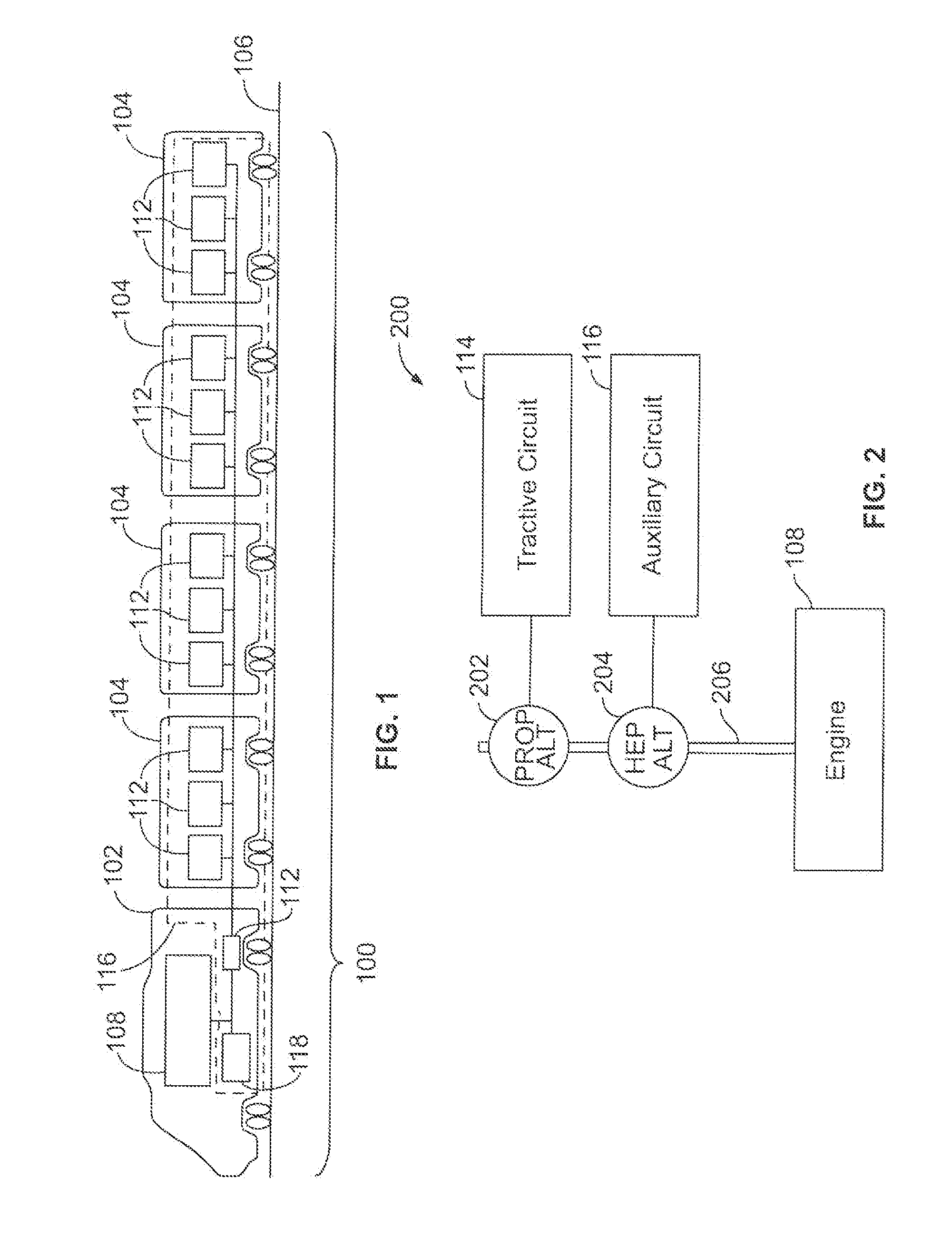
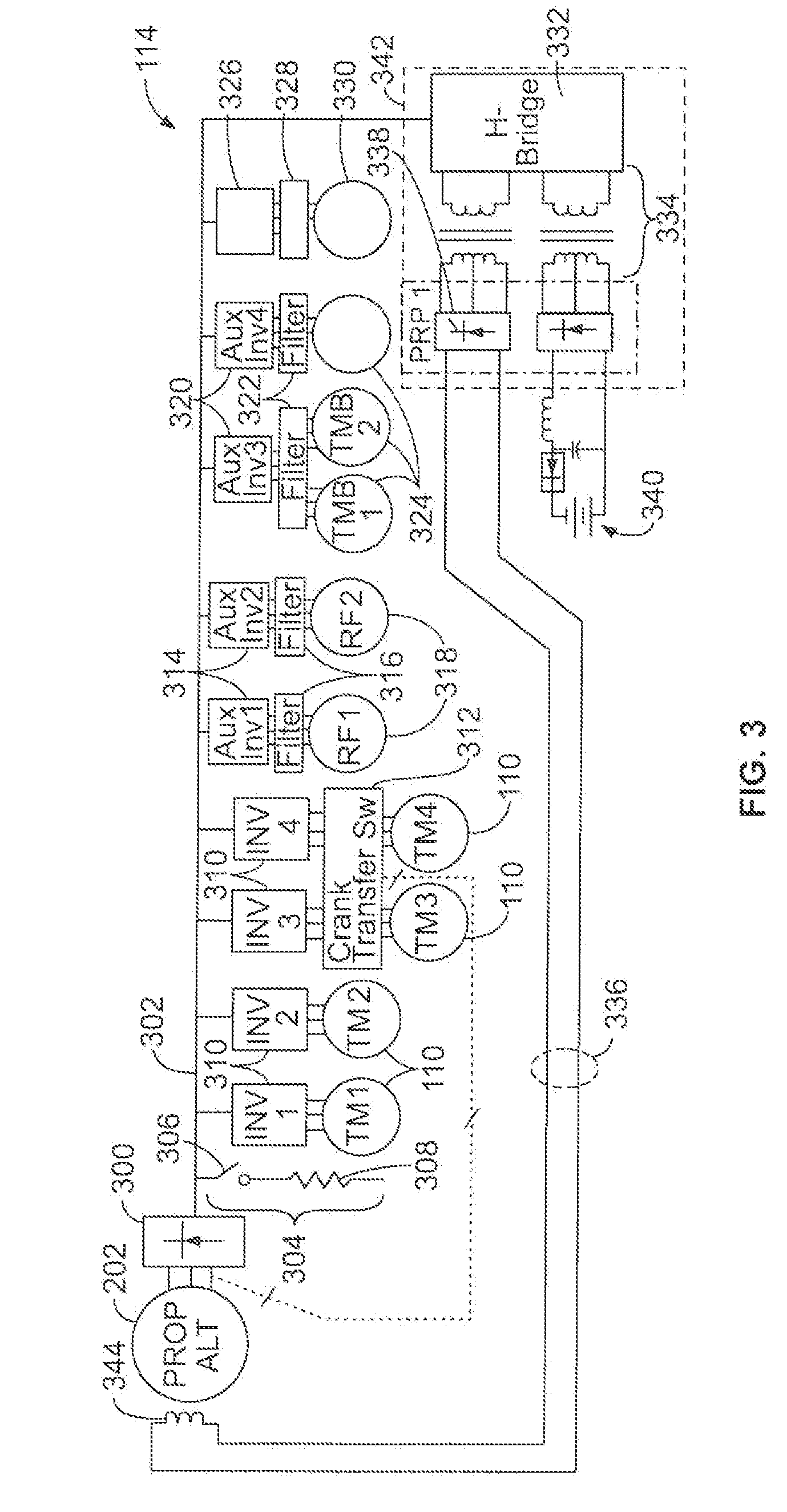
The patent text describes different power distribution systems for rail vehicles. These systems include an alternator, a bus, and a Head End Power (HEP) alternator or motor / generator set. The alternator generates electric current to power a propulsion electric load, while the HEP alternator or motor / generator set generates electric current to power a non-propulsion electric load. In some embodiments, the system may also include a first and second bus to separate the HEP alternator or motor / generator set from the propulsion alternator or bus. The technical effects of these systems include improved efficiency and versatility in power distribution for rail vehicles.

Problems solved by technology

Such a running engine may create substantial and undesirable acoustic noise.
The transformers, boost choppers, and / or filters that are used to change the voltage or filter the current transferred between the tractive and auxiliary circuits may be relatively heavy and may substantially contribute to the weight of the rail vehicle.
With increasing weight comes an increasing power demand of the tractive circuit and fuel consumption to propel the rail vehicles.
The inclusion of two or more engines to separately meet the power demands of the tractive and auxiliary circuits adds substantial cost and weight to the rail vehicle.
For example, the use of two engines may increase the costs in maintaining the rail vehicle, and the weight of the rail vehicle is increased by the additional engine.

Method used


Image

  • Powered distribution systems for powered rail vehicles
  • Powered distribution systems for powered rail vehicles
  • Powered distribution systems for powered rail vehicles

Examples


Embodiment Construction

[0018]The foregoing summary, as well as the following detailed description of certain embodiments of the inventive subject matter, will be better understood when read in conjunction with the appended drawings. To the extent that the figures illustrate diagrams of the functional blocks of various embodiments, the functional blocks are not necessarily indicative of the division between hardware circuitry. Thus, for example, one or more of the functional blocks (for example, processors or memories) may be implemented in a single piece of hardware (for example, a general purpose signal processor, microcontroller, random access memory, hard disk, and the like). Similarly, the programs may be stand alone programs, may be incorporated as subroutines in an operating system, may be functions in an installed software package, and the like. The various embodiments are not limited to the arrangements and instrumentality shown in the drawings.

[0019]As used herein, an element or step recited in t...


PUM


Abstract

A power distribution system for a rail vehicle includes a propulsion alternator, a first bus, a Head End Power (HEP) alternator, and a second bus. The propulsion alternator is joined to an engine of the rail vehicle. The first bus is joined with the propulsion alternator and is configured to electrically couple the propulsion alternator with a propulsion electric load that propels the rail vehicle. The HEP alternator is joined to the engine. The second bus is joined with the HEP alternator and is adapted to electrically couple the HEP alternator with a non-propulsion electric load of the rail vehicle. The propulsion alternator generates a first electric current to power the propulsion electric load and the HEP alternator separately generates second electric current to power the non-propulsion electric load. The HEP alternator and the second bus are electrically separate from the propulsion alternator and the first bus.

Description

CROSS-REFERENCE TO RELATED APPLICATION[0001]This application is a divisional of U.S. application Ser. No. 12 / 774,757, filed May 6, 2010, the entire disclosure of which is incorporated by reference.FIELD[0002]The subject matter described herein relates generally to powered rail vehicles.BACKGROUND[0003]Some known powered rail vehicles include one or more powered units and, in certain cases, one or more non-powered trailing units. The powered units supply tractive force to propel the powered units and trailing units. A “non-powered” unit generally encompasses any rail car without an on-board source of motive power. The non-powered trailing units hold passengers and / or goods. In some cases, the powered units may be referred to as locomotives and may include one or more traction motors. An alternator may be joined with an engine of the powered unit to generate electric current. The current is supplied to tractive motors that provide the motive force that propels the rail vehicle. The po...

Claims


Application Information

Patent Timeline
Patent Type & Authority Applications(United States)
IPC IPC(8): B60R16/03B60L50/10B60L50/13
CPCB60L1/00B60L11/02Y02T10/70B60L2200/26B60R16/03B60L15/32B60L50/10B60L15/007
Inventor KUMAR, AJITH KUTTANNAIR
Owner GE GLOBAL SOURCING LLC
Learn More