Integrated high-voltage direct current electric power generating system

a high-voltage direct current and power generation system technology, applied in the direction of electric generator control, generator circuit arrangement control, association for rectification, etc., can solve the problems of increased overall system size and prone to reliability problems

Inactive Publication Date: 2013-08-01
HAMILTON SUNDSTRAND CORP
View PDF1 Cites 7 Cited by
  • Summary
  • Abstract
  • Description
  • Claims
  • Application Information

AI Technical Summary

Problems solved by technology

An active rectifier of this configuration leads to increased size of the overall system and may be prone to reliability issues.
Additionally, although the resolver-based position sensor used for active rectifier switch commutation is effective, such a component also may provide reliability concerns.

Method used


Image

  • Integrated high-voltage direct current electric power generating system
  • Integrated high-voltage direct current electric power generating system

Examples


Embodiment Construction

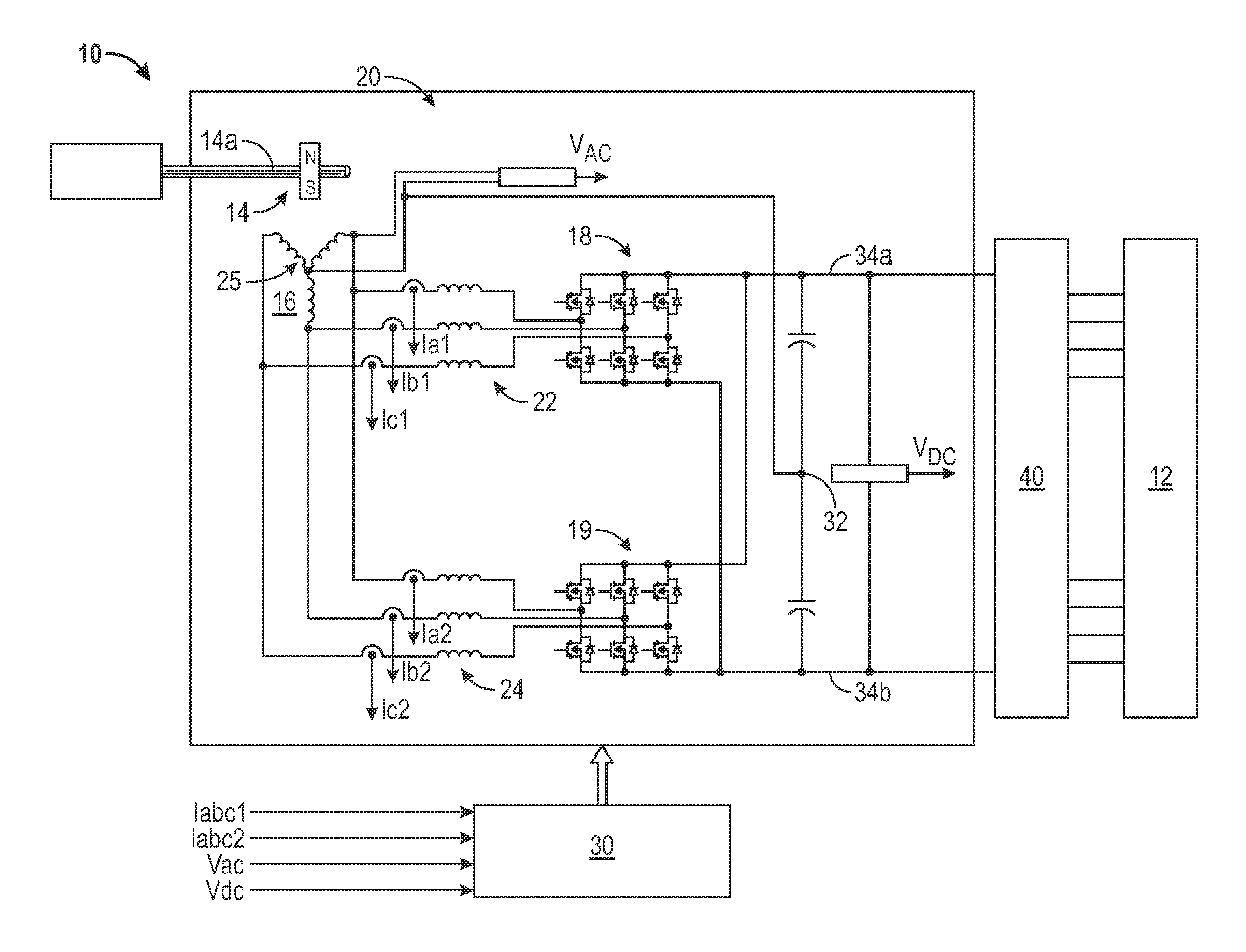
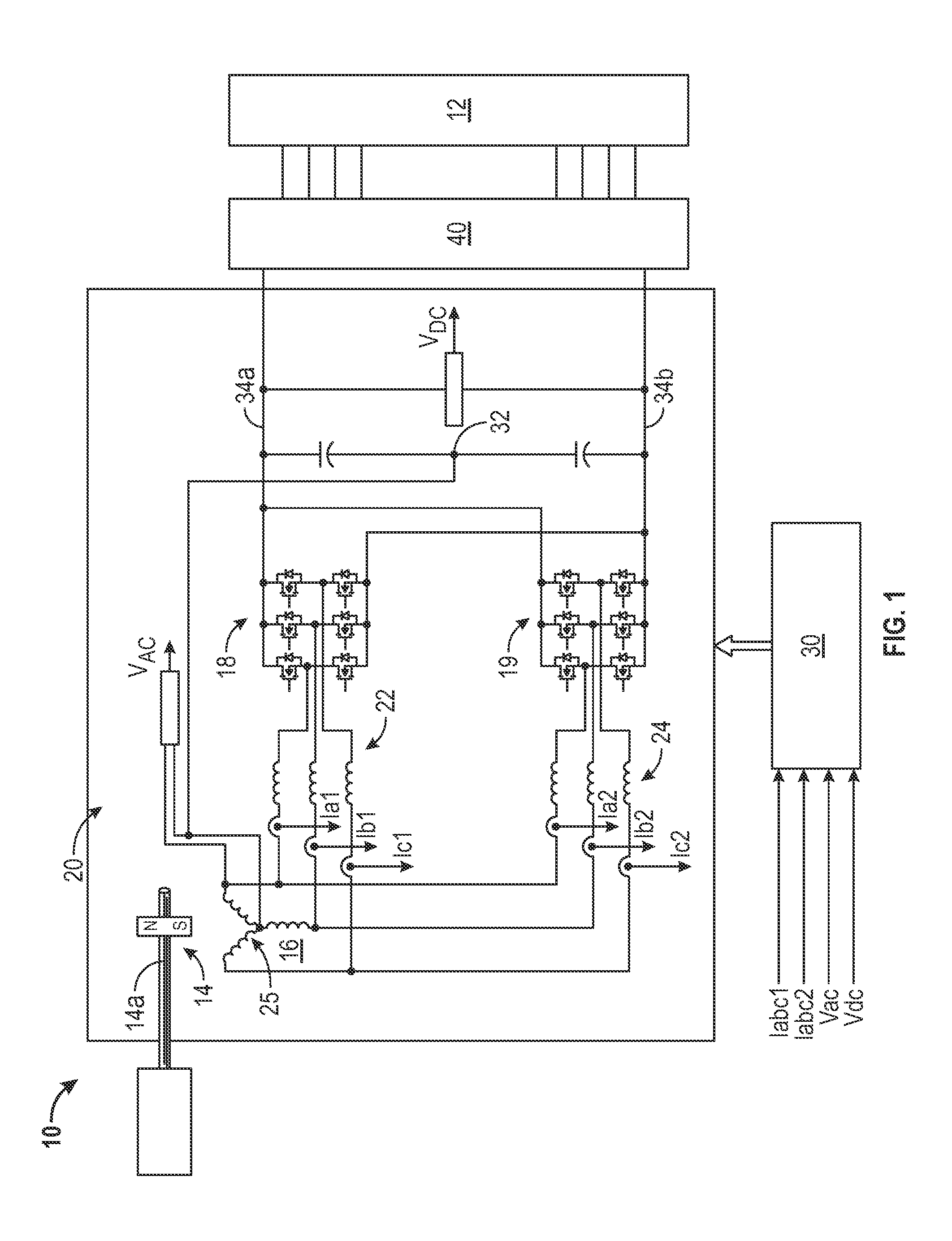
[0007]Referring to FIG. 1, an electric power generating system (EPGS) is schematically illustrated and generally referred to with reference numeral 10. The EPGS 10 is operably connected to at least one load 12 that is to be driven by the EPGS 10. The at least one load 12 may be components or systems associated with numerous applications, with one such application including, but not being limited to, vehicles, such as military ground vehicles.

[0008]The EPGS 10 is an integrated high-voltage direct current (HVDC) system and comprises a permanent magnet generator (PMG) 14 that includes a PMG stator 16 and a PMG rotor 14a The PMG stator 16 includes an armature winding 25 The EPGS 10 also includes a first rectifier 18 and a second rectifier 19. The PMG 14, the PMG armature winding 25, the first rectifier 18 and the second rectifier 19 are all disposed within a PMG housing 20. Also disposed within the PMG housing 20 is a plurality of boost inductors, such as a first boost inductor 22 and a...


PUM


Abstract

An integrated high-voltage direct current (HVDC) electric power generating system (EPGS) comprises a permanent magnet generator (PMG) including a PMG stator and a PMG rotor, wherein the PMG is disposed within a PMG housing. Also included is an armature winding operably connected to the PMG and a first rectifier for converting high-voltage AC from the armature winding, wherein the armature winding is in communication with a first boost inductor, wherein the armature winding, the first rectifier and the first boost inductor are each disposed within the PMG housing. The armature winding is operably connected to a second rectifier for converting high-voltage AC from the armature winding, wherein the armature winding is in communication with a second boost inductor, wherein the armature winding, the second rectifier and the second boost inductor are each disposed within the PMG housing.

Description

BACKGROUND OF THE INVENTION[0001]The present invention relates to power generation systems, and more particularly to a high-voltage direct current (HVDC) power generation system.[0002]HVDC power generating systems often employ a permanent magnet generator (PMG) that is coupled with an active rectifier. Typical topology of such a system utilizes PMG stator self-inductance as a boost inductor and a position sensor, such as a resolver, is used for active rectifier switch commutation. The active rectifier often is a stand-alone line replaceable unit (LRU) connected to the PMG via a three-phase power cable, as well as with a resolver cable. An active rectifier of this configuration leads to increased size of the overall system and may be prone to reliability issues. Additionally, although the resolver-based position sensor used for active rectifier switch commutation is effective, such a component also may provide reliability concerns.BRIEF DESCRIPTION OF THE INVENTION[0003]According to ...

Claims


Application Information

Patent Timeline
Patent Type & Authority Applications(United States)
IPC IPC(8): H02K11/04
CPCH02P9/00H02M7/23H02P9/009H02P9/02H02P9/48
Inventor ROZMAN, GREGORY I.GIERAS, JACEK F.MOSS, STEVEN J.
Owner HAMILTON SUNDSTRAND CORP
Why Eureka
Try Eureka