Method for current differential protection of direct current electric transmission line

A current differential and power transmission line technology, applied in emergency protection circuit devices, electrical components, etc., can solve problems such as easy misoperation, slow protection action speed, poor performance, etc., and achieve high reliability and fast action speed

Inactive Publication Date: 2009-11-11
XI AN JIAOTONG UNIV
View PDF0 Cites 45 Cited by
  • Summary
  • Abstract
  • Description
  • Claims
  • Application Information

AI Technical Summary

Problems solved by technology

However, judging from the operation of the existing DC transmission projects, the DC line relay protection devices put into operation at home and abroad have problems such as incomplete theory, no universally applicable setting principles, and the setting only depends on the simulation results for setting, which leads to The reliability of DC line protection is not high
[0004] The current differential protection has excellent performance and is the natural main protection in AC transmission lines. However, due to various reasons, its protection action speed is slow and the performance is not good in DC transmission lines.
Most of the DC lines in operation use traveling wave protection as the main protection. Traveling wave protection operates quickly and is not affected by factors such as transition resistance, load, and long-line distributed capacitance, but its reliability is not high and it is easy to malfunction

Method used


Image

  • Method for current differential protection of direct current electric transmission line
  • Method for current differential protection of direct current electric transmission line
  • Method for current differential protection of direct current electric transmission line

Examples


Embodiment Construction

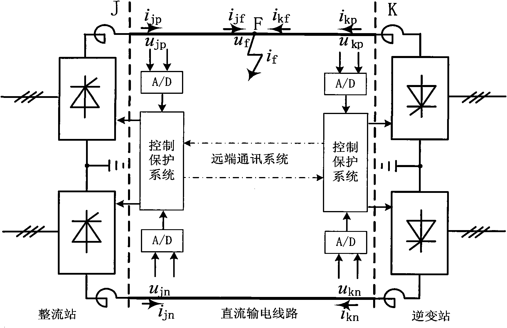
[0029] The DC transmission system consists of three parts: rectifier station, inverter station and DC transmission line. The rectifier station converts the alternating current to direct current, the transmission line transmits the direct current to the opposite inverter station, and the inverter station converts the direct current to alternating current. The core content of the invention is to provide protection for direct current transmission lines.

[0030] refer to figure 1 As shown, it consists of three parts: rectifier station, inverter station and DC transmission line. F in the figure is the fault point of the DC line, u jp i jp are the DC voltage and DC current at the positive pole of the rectifier side, respectively; u jn i jn is the DC voltage and DC current at the negative pole of the rectifier side; u kp i kp are the DC voltage and DC current at the positive pole of the inverter side, respectively; u kn i kn are the DC voltage and DC current of the negative...


PUM


Abstract

The invention discloses a method for current differential protection of a direct current electric transmission line, which comprises the following steps: according to a distributed parameter model of the electric transmission line, using mode transformation in a time domain to transform sampling values of direct current and direct current voltage into a modulus; then using the mode voltage and the current of two ends from two ends of a line respectively to calculate mode current of certain point of the line at each moment; and using the mode current to directly construct a current differential protection criterion, or synthesizing electrode current through electrode mode inverse transformation, and then constructing the current differential protection criterion according to the electrode current. The method can improve the sensitivity and the reliability of direct current line protection, has good controllability and high security, has a complete setting theory, overcomes the defects of the conventional traveling-wave protection as the main protection of a high-voltage direct current line, and requires no recognition of a traveling-wave wave head; besides, the calculation is simple. The method is mainly used for the current differential protection of the direct current electric transmission line in an electric power system, in particular for the protection of an ultra / extra high-voltage direct current electric transmission line.

Description

technical field [0001] The invention relates to the field of relay protection for direct current transmission lines in power systems, in particular to current differential protection for super / extra high voltage direct current transmission lines. Background technique [0002] High-voltage direct current (HVDC) transmission has the advantages of large transmission power, low line cost, and good control performance. It occupies an increasingly important position in long-distance and high-power transmission. Developed countries in the world regard it as a large-capacity, long-distance The main means of power transmission and asynchronous networking, my country has also become a hot spot in power construction because of "power transmission from west to east, mutual supply between north and south, and national networking". Since Gezhouba-Shanghai adopted DC transmission in 1989, the number of DC transmission projects in my country has ranked first in the world. [0003] The HVDC ...

Claims


Application Information

Patent Timeline
Patent Type & Authority Applications(China)
IPC IPC(8): H02H7/26
Inventor 宋国兵索南加乐高淑萍焦在宾
Owner XI AN JIAOTONG UNIV
Why Eureka
Try Eureka