Liquid ejection head and liquid ejection apparatus

a liquid ejection and apparatus technology, applied in electrical devices, piezoelectric/electrostrictive/magnetostrictive devices, printing, etc., can solve the problems of concentrated distortion, increased liquid ejection by piezoelectric element flexing, etc., to prevent or reduce problems, increase the amount of liquid to be ejected

Active Publication Date: 2013-08-01
SEIKO EPSON CORP
View PDF2 Cites 19 Cited by
  • Summary
  • Abstract
  • Description
  • Claims
  • Application Information

AI Technical Summary

Benefits of technology

[0006]An advantage of some aspects of the invention is that a liquid ejection head capable of preventing or reducing a problem such as cracking in a piezoelectric layer and increasing the amount of liquid to be ejected, and a liquid ejection apparatus having the same are provided.
[0007]According to an aspect of the invention, a liquid ejection head includes: a substrate in which a pressure generating chamber that communicates with a nozzle opening is formed; and a piezoelectric element having a piezoelectric layer, a first electrode that is formed on a surface of the piezoelectric layer on a side of the substrate so as to correspond to the pressure generating chamber, and a second electrode that is formed on a surface of the piezoelectric layer opposite to the side on which the first electrode is formed so as to extend over a plurality of the pressure generating chambers, wherein the second electrode is formed to extend to an outside of the pressure generating chamber in a longitudinal direction of the pressure generating chamber. With this configuration, the second electrode is formed to extend to the outside of the pressure generating chamber in the longitudinal direction of the pressure generating chamber. Accordingly, concentration of distortion at the interface on the piezoelectric element is reduced compared to the case in which the second electrode is formed not to extend to the outside of the pressure generating chamber in the longitudinal direction, thereby reducing a problem such as cracking. Further, since the resistance to cracking of the piezoelectric element is improved, voltage resistance to the piezoelectric element is also improved.
[0008]According to an aspect of the invention, an area where the first electrode, the piezoelectric layer and the second electrode overlap may be formed to extend to an outside of the pressure generating chamber in the longitudinal direction. That is, since the area where the first electrode, the piezoelectric layer and the second electrode overlap (active section) is an area which drives when a voltage is applied, concentration of distortion at the interface on the piezoelectric element is reduced by providing the active section to extend to the outside of the pressure generating chamber in the longitudinal direction, thereby reducing a problem such as cracking.
[0009]According to an aspect of the invention, an opening is formed on the piezoelectric layer by removing the piezoelectric layer at a position that substantially corresponds to an area between the pressure generating chambers, and the opening may be formed to extend to an outside of the pressure generating chamber in the longitudinal direction. With this configuration, since the opening is formed to extend to the outside of the pressure generating chamber in the longitudinal direction, a displacement amount of the piezoelectric element at the end portions of the pressure generating chamber increases, which results in increased amount of liquid ejected by flexing of the piezoelectric element.
[0010]According to an aspect of the invention, a metal layer that is disposed on the second electrode and serves as a wiring may be formed to extend to both inside and outside of the pressure generating chamber. With this configuration, since the metal layer is formed to extend to both inside and outside of the pressure generating chamber, concentration of distortion at the interface on the piezoelectric element is further reduced, thereby reducing a problem such as cracking.

Problems solved by technology

During flexing, a significant amount of stress is generated at the interface between an area on the piezoelectric element where the upper electrode, the piezoelectric layer and the lower electrode overlap (active section) and an area other than the active section (inactive section), which causes distortion to be concentrated at this position.
Since concentration of distortion may cause a problem such as crack in the piezoelectric layer that forms the piezoelectric element, it has been required to prevent such a problem.
With this configuration, since the opening is formed to extend to the outside of the pressure generating chamber in the longitudinal direction, a displacement amount of the piezoelectric element at the end portions of the pressure generating chamber increases, which results in increased amount of liquid ejected by flexing of the piezoelectric element.

Method used


Image

  • Liquid ejection head and liquid ejection apparatus
  • Liquid ejection head and liquid ejection apparatus
  • Liquid ejection head and liquid ejection apparatus

Examples


Embodiment Construction

1. General Configuration of Liquid Ejection Head

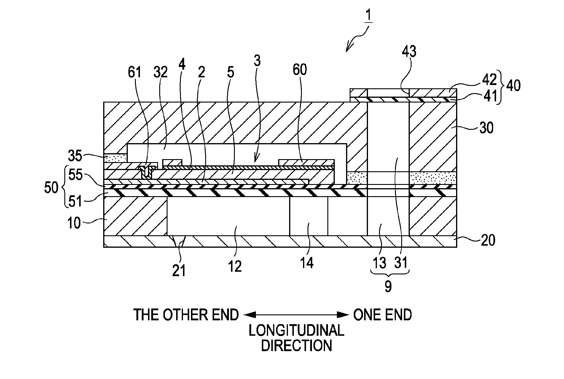
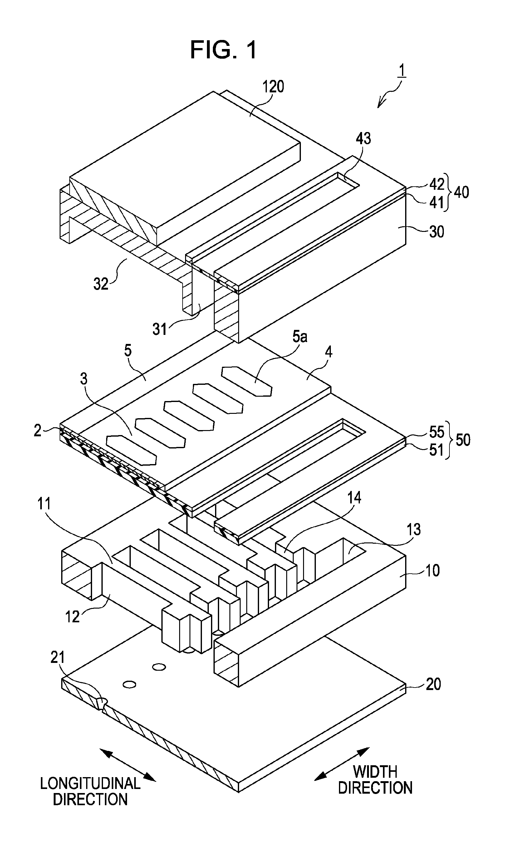
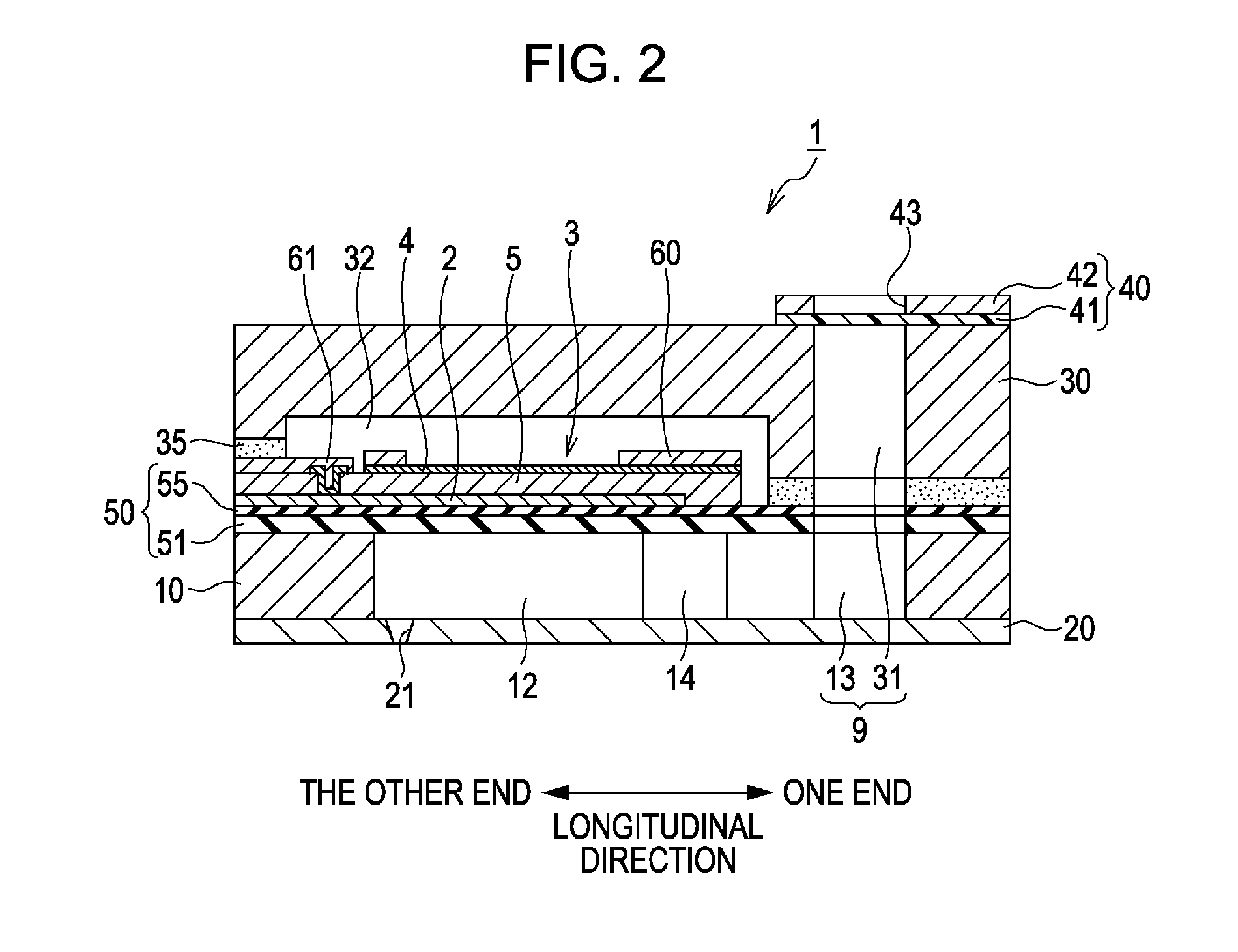
[0022]An embodiment of the invention will be described below with reference to the drawings. FIG. 1 is an exploded perspective view which schematically shows an ink jet recording head 1 (hereinafter, referred to as recording head 1) which is an example of liquid ejection head. FIG. 2 is a vertical sectional view of the recording head 1 in a plane parallel to the longitudinal direction of a pressure generating chambers 12 and passing through a lower electrode film 2 that corresponds to one of the pressure generating chambers 12. The recording head 1 includes a substrate (flow path forming substrate) 10. The substrate 10 is formed of, for example, a silicon single crystal substrate with a vibration plate 50 disposed on one side thereof. The vibration plate 50 includes, for example, an elastic film 51 formed of an oxide film that is in contact with the substrate 10, and an insulator film 55 formed of an oxide film made of a material diffe...


PUM


Abstract

A liquid ejection head includes a substrate in which a pressure generating chamber that communicates with a nozzle opening is formed; and a piezoelectric element having a piezoelectric layer, a first electrode that is formed on a surface of the piezoelectric layer on a side of the substrate so as to correspond to the pressure generating chamber, and a second electrode that is formed on a surface of the piezoelectric layer opposite to the side on which the first electrode is formed so as to extend over a plurality of the pressure generating chambers, wherein the second electrode is formed to extend to an outside of the pressure generating chamber in a longitudinal direction of the pressure generating chamber.

Description

BACKGROUND[0001]1. Technical Field[0002]The present invention relates to liquid ejection heads and liquid ejection apparatuses.[0003]2. Related Art[0004]JP-A-2009-172878 and JP-A-2009-196329 disclose a liquid ejection head including a substrate in which a pressure generating chamber that communicates with a nozzle opening for ejecting liquid is formed, and a piezoelectric element having a piezoelectric layer, a lower electrode that is formed on the lower side of the piezoelectric layer and an upper electrode that is formed on the upper side of the piezoelectric layer. In such a liquid ejection head, the lower electrode is provided as an individual electrode that corresponds to each of the pressure generating chambers, and the upper electrode is provided as a common electrode for a plurality of piezoelectric elements that correspond to a plurality of pressure generating chambers.[0005]The above-mentioned piezoelectric element displaces when a voltage is applied across both electrodes...

Claims


Application Information

Patent Timeline
Patent Type & Authority Applications(United States)
IPC IPC(8): B41J2/045
CPCB41J2/1631B41J2/1646B41J2002/14491B41J2/045H01L41/0805B41J2/161B41J2/1626B41J2/14201B41J2/14233B41J2/14274B41J2002/14258H10N30/871H10N30/1051
Inventor HIRAI, EIJUYAZAKI, SHIROSUMI, KOJITAKABE, MOTOKIKATO, JIROITO, HIROSHISHIMIZU, TOSHIHIROKAMIJO, TAKAHIROTORIMOTO, TATSUROKOJIMA, CHIKARA
Owner SEIKO EPSON CORP
Why Eureka
Try Eureka