Calibration Phantom Device and Analysis Methods

a technology of which is applied in the field of calibration phantom device and analysis method, can solve the problems of inability to transmit the performance of the acquisition device, significant amount of manual labor in the process, and inability to perform calibration

Inactive Publication Date: 2013-08-01
KITWARE
View PDF6 Cites 15 Cited by
  • Summary
  • Abstract
  • Description
  • Claims
  • Application Information

AI Technical Summary

Benefits of technology

[0037]protocols allowing a user to set performanc

Problems solved by technology

The process involves a significant amount of manual labor and, as a result, a calibration is performed at intervals of weeks or months.
In addition, the performance of the acquisition device is not transmitted to downstream clinical applications which could use the acquisition characteristics to perform improved performance such as improved disease detection and/or measurement.
This approach to calibration does not provide calibration information such as resolution, noise, and CT number bias for an individual CT scan.
Several small devices have been developed and tested with limited success.
First, the performance of an acquisition is highly dependent on the position at which the measurement is taken with respect to the center of rotation (isocenter) of the CT scanner. Thus a calibration measurement must always be compared to a reference measurement that was acquired with similar conditions and at the same distance from isocenter to determine if the individual CT acquisition is within an acceptable performance range. To avoid this complexity, most traditional calibration phantoms obtain measurements at a fixed distance and close to isocenter and therefore do not fully characterize the spatial variation present in a CT acquisition.
Second, calibration devices made to date have view

Method used


Image

  • Calibration Phantom Device and Analysis Methods
  • Calibration Phantom Device and Analysis Methods
  • Calibration Phantom Device and Analysis Methods

Examples


Embodiment Construction

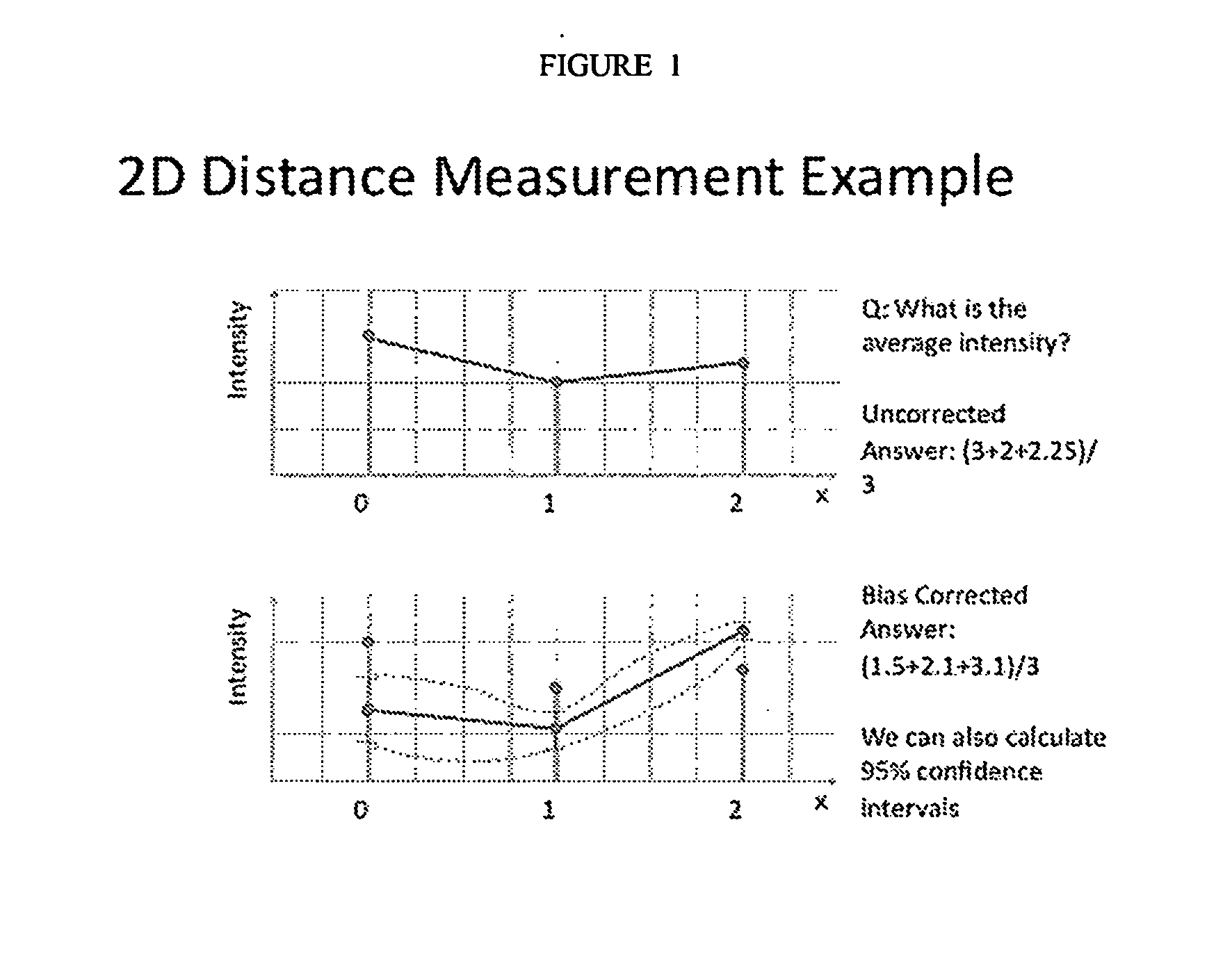
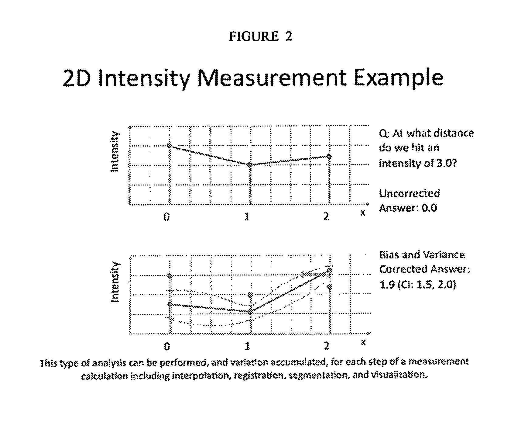
[0051]One aspect of the present invention is directed to a virtual model that optimizes the scanned information received from a radiologic device such as a CT scanner by taking into account the variations that occur during scanning whereby the scanner reports different values at different distances from the center of a scan. Such a model comprises a set of values stored within a database and which can be used to correct or optimize the actual values generated during a radiologic scan such as a CT scan.

[0052]In another aspect, the database is updated with each new scan performed.

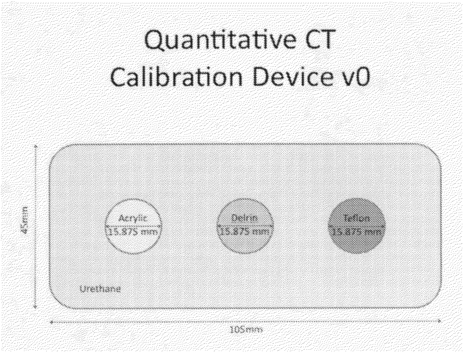
[0053]In another aspect, the database is created by scanning a pocket phantom, or small scannable device, that provides resolution and other information about the performance of the scanner being used.

[0054]In another aspect, the scannable device or phantom may have detectable indicia, such as a serial number. In another aspect, the phantom has a moving part integrated in it that, when moving at a constant ro...


PUM


Abstract

This invention relates to a small pocket phantom designed to estimate the fundamental properties of imaging scanning acquisition including 3D resolution, noise, and scanner attenuation performance for different materials, together with an automated phantom analysis algorithm.

Description

CROSS REFERENCE TO RELATED APPLICATIONS[0001]Not applicable.STATEMENT REGARDING FEDERALLY SPONSORED RESEARCH OR DEVELOPMENT[0002]No federal government funds were used in researching or developing this invention.NAMES OF PARTIES TO A JOINT RESEARCH AGREEMENT[0003]Not applicable.REFERENCE TO A SEQUENCE LISTING[0004]Not applicable.BACKGROUND[0005]1. Field of the Invention[0006]This invention relates to a device, system, software, and methods for quantitatively measuring fundamental image acquisition characteristics of a CT scan and collections of CT scans. This can be used for measuring the performance of an individual acquisition, measuring and monitoring the performance of an imaging device, or measuring and monitoring the performance of a collection of images from a set of imaging devices utilized in a clinical study. The methods described here can also be used to perform precise measurements of structures in CT images.[0007]2. Background of the Invention[0008]Calibration of CT scan...

Claims


Application Information

Patent Timeline
IPC IPC(8): G01T1/16
CPCA61B5/055G01T1/16G01T1/169A61B6/583
Inventor AVILA, RICARDOKRISHNAN, KARTHIK
Owner KITWARE
Why Eureka
Try Eureka