
Wave-driven blower and electric motor/generator

a technology of electric motors and generators, applied in the field of heat transfer, can solve problems such as safety issues of conventional motors that use permanent magnets, and achieve the effects of reducing safety hazards of conventional motors and generators, reducing safety hazards, and reducing the number of prior motors/generators

Inactive Publication Date: 2013-08-01
EPSTEIN RICHARD
View PDF0 Cites 3 Cited by
  • Summary
  • Abstract
  • Description
  • Claims
  • Application Information

AI Technical Summary

Benefits of technology

The present invention is about using piezoelectric actuators to regulate magnetic reluctance to drive magnetically powered electric motors or generators. This approach has advantages over conventional motors and generators. The piezoelectric actuators have high power densities, and the hysteresis losses are low. The architecture of the generator or motor minimizes eddy current losses and heating of permanent magnets. PARS motors and generators are also safer because they produce power only when the actuated is activated.

Problems solved by technology

(7) Conventional motors that use permanent magnets have safety issues because voltages are produced whenever the rotor is spinning, regardless of whether output power is desired.

Method used

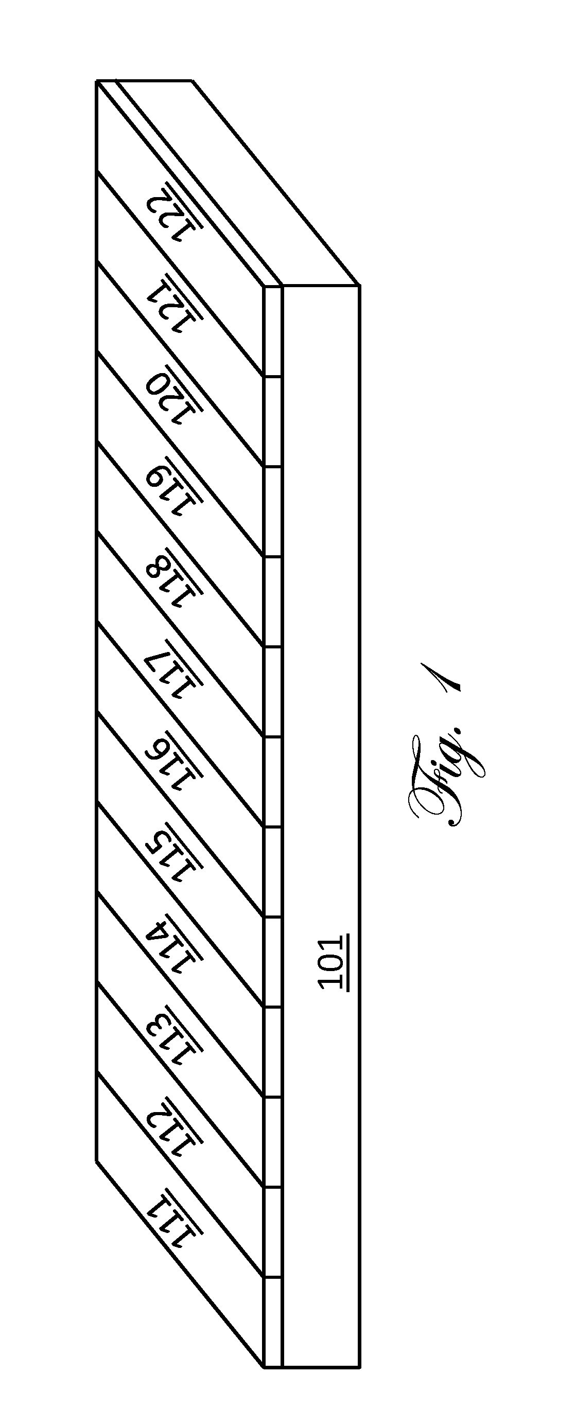
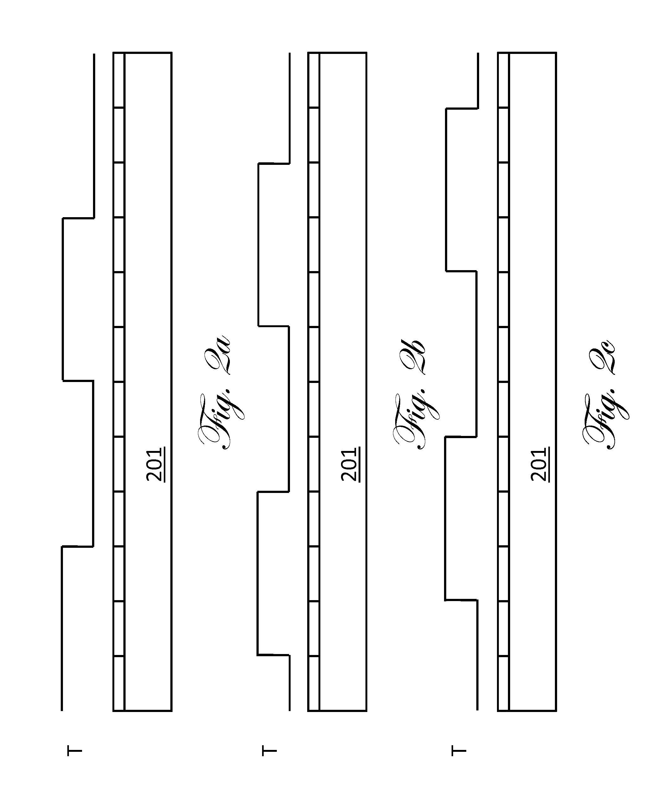

Image

  • Wave-driven blower and electric motor/generator
  • Wave-driven blower and electric motor/generator
  • Wave-driven blower and electric motor/generator

Examples


example embodiment

[0062]FIG. 7 is a schematic illustration of a single heat fin in an example embodiment of the present invention. The heat fin 701 comprises a substantially rigid material with high thermal and electrical conductivities, for example copper or aluminum.

[0063]FIG. 8 is a schematic illustration of an electrically insulating gasket. The gasket 801 can comprise any electrically insulating material that also provides a good seal for containing liquid crystals. The insulating gaskets mount between the electrodes and the heat fins. The gaskets electrically insulate the electrodes from the fins. The gaskets also create cavities between the heat fin and the electrodes for holding liquid crystal material.

[0064]FIG. 9 is an illustration of a single electrode 902 with an electrical wired 901 connected to it. The electrical wire 901 connects to the control electronics, which sets the voltage of the electrode relative to the heat fin.

[0065]FIG. 10 is an illustration of a set of electrodes 902 with ...


PUM


Abstract

The present invention provides a wave-driven blower and a wave-driven generator. Embodiments can accelerate fluid flows with waves requiring with no or minimal moving parts. The waves driving the flow can be surface-thermal waves on the walls of the device. The velocity of the surface-thermal wave entrains the fluid near the surface and imparts a velocity to the fluid. Other types of waves can generate fluid flow. These other waves can be produced by variations in chemical composition, ionic concentration, chemical potential, total pressure, partial pressure and surface texture. Operating as a generator, the device extracts energy from a flowing fluid to amplify wave motions. The wave motions in turn generate electrical power or some other form of useable power

Description

TECHNICAL FIELD[0001]The present invention is related to the field of heat transfer, and more particularly to production of airflow across heat transfer surfaces, and to the field of electric motors and generators.BACKGROUND ART[0002]This application claims the benefit of U.S. provisional application 61 / 393,138, filed Oct. 14, 2010, which is incorporated herein by reference.[0003]Previous inventions for creating airflows and for cooling electronic devices have used electric fans to increase airflows thorough cooling fins. U.S. Pat. No. 7,647,960 and U.S. Pat. No. 7,701,718 describe a means for heat dissipation using separate cooling fins and electric fans to remove heat. Piezoelectric or otherwise electroactuated fans and pumps use mechanical traveling waves or peristaltic action to generate flows. U.S. Pat. No. 5,192,197 and U.S. Pat. No. 5,961,298 describe generating flows from macroscopic motions of the surfaces of chambers that progress as traveling waves. All prior approaches r...

Claims


Application Information

Patent Timeline
IPC IPC(8): F01D25/12
CPCH01L41/09F01D25/12F04F7/00F04B19/20F04B19/006
Inventor EPSTEIN, RICHARD
Owner EPSTEIN RICHARD
Learn More