Hollow airfoil construction utilizing functionally graded materials

a technology of functional grade materials and hollow airfoils, which is applied in the direction of blade accessories, machines/engines, chemical vapor deposition coatings, etc., can solve the problems of large profile of fan blades, time-consuming and expensive manufacturing,

Active Publication Date: 2013-08-01
RTX CORP
View PDF7 Cites 40 Cited by
  • Summary
  • Abstract
  • Description
  • Claims
  • Application Information

AI Technical Summary

Problems solved by technology

One result is the fan blades may become larger in profile.
While these fan blades have desirable functional characteristics, they are also somewhat time consuming and expensive to manufacture.
Fan blades are exposed to ingestion of foreign objects, and result in damage.

Method used


Image

  • Hollow airfoil construction utilizing functionally graded materials
  • Hollow airfoil construction utilizing functionally graded materials
  • Hollow airfoil construction utilizing functionally graded materials

Examples


Embodiment Construction

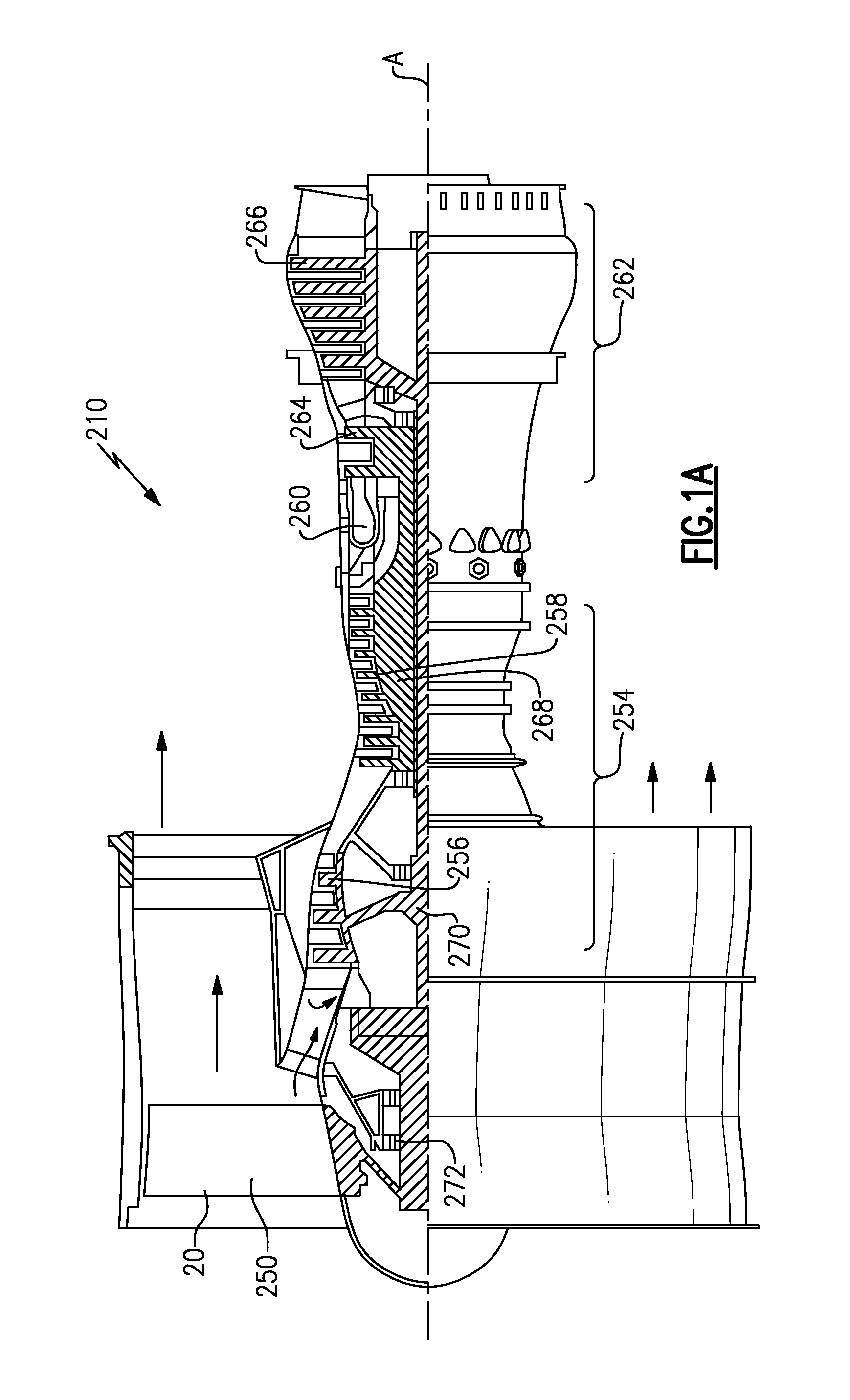
[0036]A gas turbine engine 210 is shown in FIG. 1A. As shown, the engine 210 includes a fan 250 (which includes a plurality of fan blades 20), a compressor section 254 (which includes both a low pressure compressor 256 and a high pressure compressor 258), a combustor 260, and a turbine section 262 (which includes both a high pressure turbine 264 and a low pressure turbine 266). The high pressure compressor 258 is driven, via a first spool 268, by the high pressure turbine 264. The low pressure compressor 256 is driven, via a second spool 270, by the low pressure turbine 266. Also driven by the low pressure turbine 266 are the fan blades 20 of the fan 250, which fan is coupled to the second spool 270 via a gear 272.

[0037]The fan 250 delivers air into compressor section 254. Air compressed by the compressor section is delivered into combustor 260. Products of the combustion in the combustor pass downstream over turbine section 262.

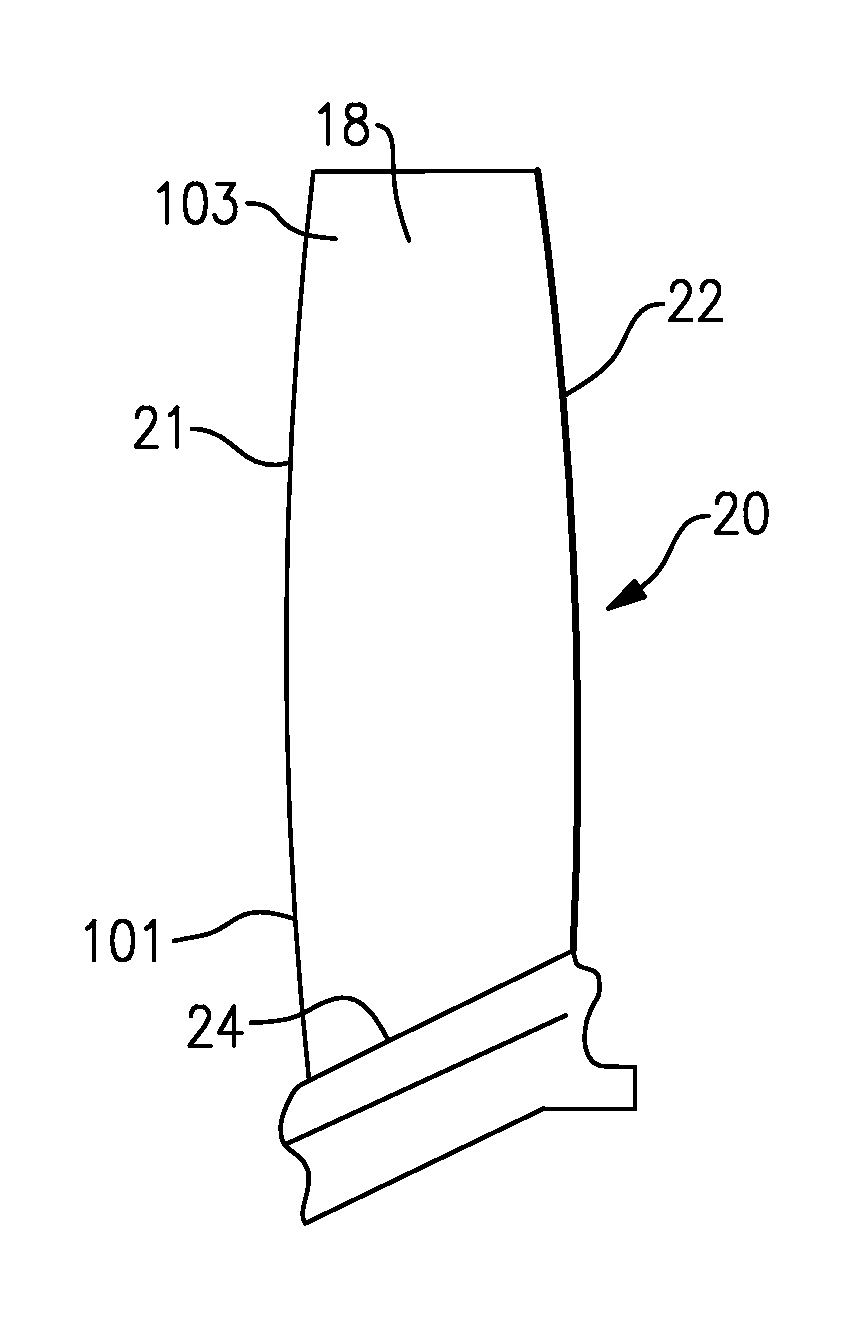
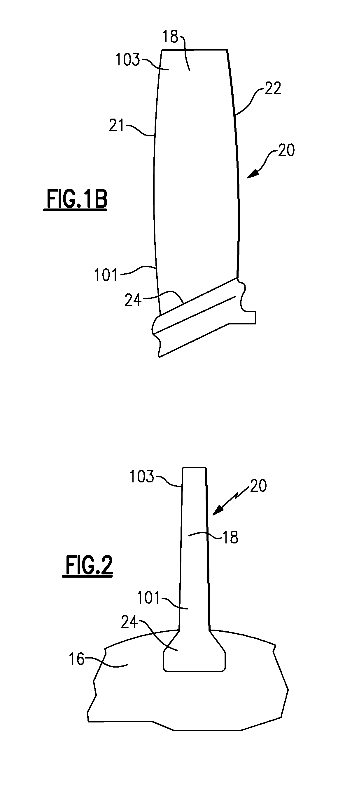
[0038]A fan blade 20 is illustrated in FIG. 1B having ...


PUM

PropertyMeasurementUnit
densitiesaaaaaaaaaa
compressive residual stressaaaaaaaaaa
suctionaaaaaaaaaa

Abstract

A method of forming an airfoil includes the steps of depositing material to form an airfoil in a first layer, and then depositing material in a second layer on the first layer. The first and second layers have distinct densities. An airfoil is also disclosed. The method provides powerful design advantages.

Description

BACKGROUND OF THE INVENTION[0001]This application relates to a method for forming airfoil structures having hollow internal spaces, wherein the airfoil structure is formed in deposited layers.[0002]Airfoils are utilized in any number of applications. In one well known application, a gas turbine engine includes blades associated with a fan section, a compressor section, and a turbine section, each of which have airfoils.[0003]Gas turbine engines typically include the fan delivering air into the compressor. The air is compressed and delivered downstream into a combustion section. The air is mixed with fuel and burned, and products of the combustion pass over the turbine. Turbine rotors are driven to rotate, and in turn drive the compressor and fan rotors.[0004]Typically in the past, a single turbine rotor drove both a low pressure compressor rotor and the fan. However, recently, geared connections have been included between the fan blade and the low pressure compressor rotor. With thi...

Claims


Application Information

Patent Timeline
Patent Type & Authority Applications(United States)
IPC IPC(8): F01D5/14B05D3/12B05D3/00B05D1/36C23C16/48
CPCF01D5/286B22F3/1055B22F5/04C22C14/00F01D5/14F05D2230/31F01D9/00F01D25/005F01D5/147F05D2220/36F01D5/28F05D2230/22B33Y10/00B33Y80/00Y02P10/25B22F12/45B22F10/50B22F10/36B22F10/38B22F10/66B22F10/25B22F12/55C23C22/73B23P15/04B33Y50/02C23C28/028C23C26/02F05D2300/611B29C64/153C23C22/70C23C14/28C23C22/72Y10T29/49339B21D53/78C23C24/10Y10T29/49336B29C64/386
Inventor EL-WARDANY, TAHANY IBRAHIMGU, WENJIONGMOSHER, DANIEL A.VIENS, DANIEL V.GUO, CHANGSHENG
Owner RTX CORP
Why Eureka
Try Eureka