Eureka AIR delivers breakthrough ideas for toughest innovation challenges, trusted by R&D personnel around the world.

Swing Barrel Type Positive Displacement Pump Using Cross Shaft Joint Bearing

a positive displacement, barrel type technology, applied in the field of pumps, can solve the problems of increasing the frequency of pump maintenance, the ball bearing cannot satisfactorily perform efficient transmission of motion, etc., to achieve the effect of shortening the life of the pump, and reducing the wear of the bearing

Inactive Publication Date: 2013-08-01
LIU DALEI +1
View PDF3 Cites 0 Cited by
  • Summary
  • Abstract
  • Description
  • Claims
  • Application Information

AI Technical Summary

Benefits of technology

The present invention is a swing barrel type positive displacement pump using cross shaft joint bearing. It is resistant to wear, improves motion transmission efficiency, and maintains good condition for a long time. Compared with the original ball bearing structure that produces sliding friction, the present invention has the advantages of minimal wearing, low energy consumption, swift rotation, high rotation speed, and long service life. It is more in line with the requirements for high efficiency and prolonged maintained condition of a positive displacement pump for a low carbon economy.

Problems solved by technology

However, since the ball bearings outside the rotating barrel adopt the structure of sliding bearings which produce sliding friction with high coefficient of friction during operation, the ball bearings cannot satisfactorily perform efficient transmission of motion.
Also, wearing of the ball bearings will increase the frequency of maintenance of the pump and thus shorten the life of the pump.

Method used


Image

  • Swing Barrel Type Positive Displacement Pump Using Cross Shaft Joint Bearing
  • Swing Barrel Type Positive Displacement Pump Using Cross Shaft Joint Bearing

Examples


Embodiment Construction

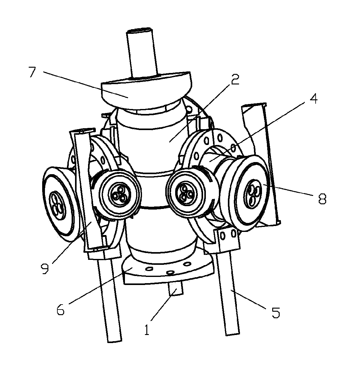
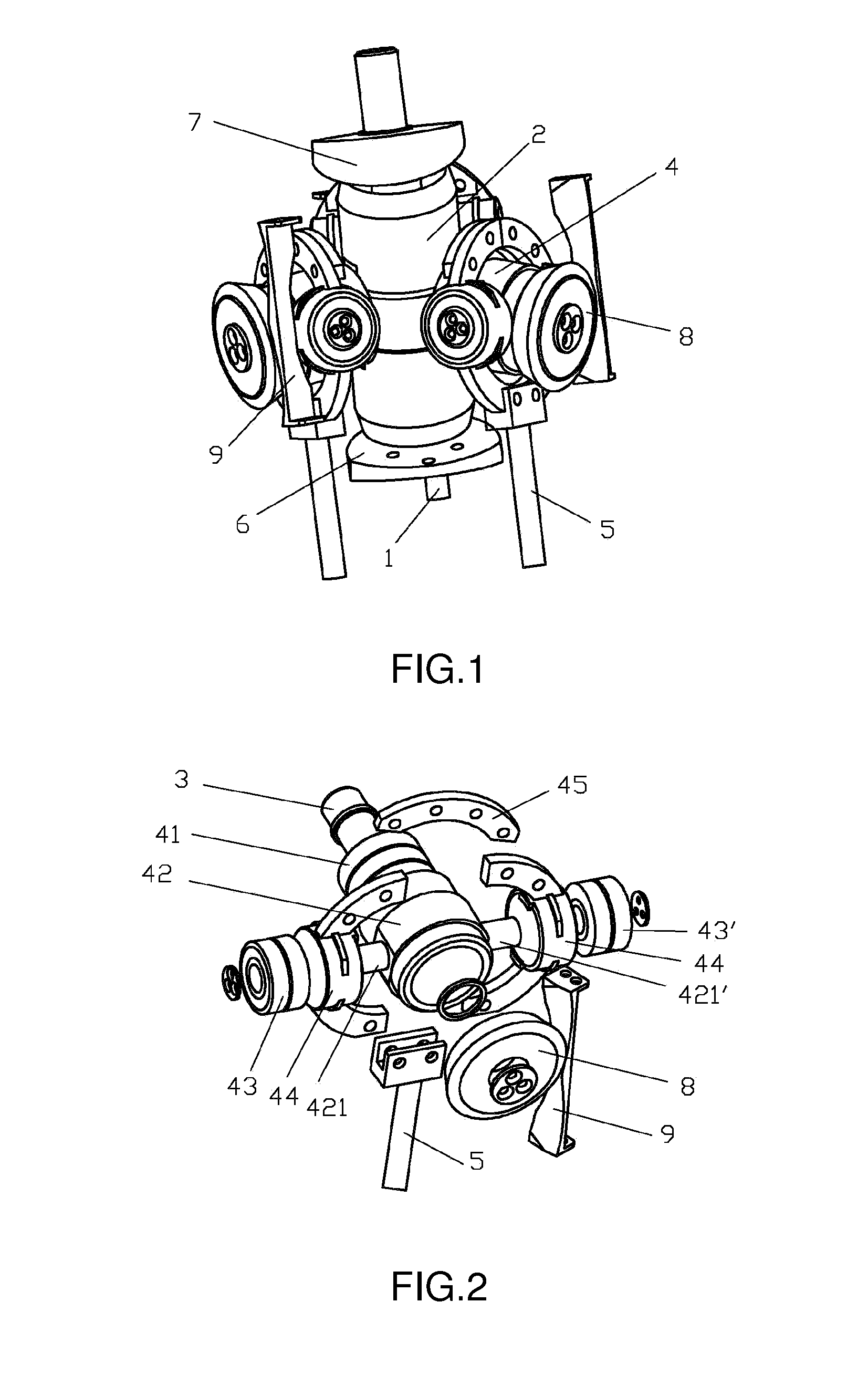
[0013]As shown in FIGS. 1-2, a swing barrel type positive displacement pump using cross shaft joint bearing comprises a positive displacement pump housing and a main shaft 1 connected with a motor; an upper part of the main shaft 1 is slantwise provided with a rotating barrel 2 which swings along with the rotation of the main shaft 1; periphery of the rotating barrel 2 is evenly provided with more than three pin shafts 3; on each of the pin shafts 3, there is sleeved with a cross shaft joint bearing 4, whereas the cross shaft joint bearing 4 includes a bearing 41 sleeved on a corresponding pin shaft of the pin shafts 3, whereas outer ring of the bearing 41 is fixedly connected with a swing sleeve 42; whereas fixed shafts 421, 421′ having a same axis and forming a cross with the corresponding pin shaft extend respectively from left and right sides of the swing sleeve 42; whereas extension from the top and bottom sides may also be an available option in actual practice; whereas the fi...


PUM


Abstract

A swing barrel type positive displacement pump using a cross shaft joint bearing includes a main shaft (1) for connecting with a motor. The upper part of the main shaft (1) is slantwise provided with a rotating barrel (2) which swings along with the rotation of the main shaft (1). The periphery of the rotating barrel (2) is evenly provided with more than three pin shafts (3). Each pin shaft (3) is sleeved with a cross shaft joint bearing (4). Each cross shaft joint bearing (4) includes a bearing (41) sleeved on the pin shaft (3). The outer ring of each bearing (41) is fixedly connected with a swing sleeve (42). Fixed shafts (421, 421′) with the same axis extend along the left and right sides of the swing sleeve (42), respectively. The fixed shafts (421,421′) are sleeved with a left and right bearing (43, 43′), respectively. The outer rings of the left and right bearings are fixedly connected with left and right cross shaft swing sleeves (44, 44′), respectively. The top ends of the left and right cross shaft swing sleeves (44, 44′) are fixedly connected with each other. The bottom ends of the left and right cross shaft swing sleeves (44, 44′) are fixedly connected with a connecting bar (5) which is hinged with a piston in a displacement chamber. The positive displacement pump has low wear, low energy consumption, sensitive rotation, high rotation speed, and long service life.

Description

BACKGROUND OF THE INVENTION[0001]The present invention relates to a kind of pump, and more specifically relates to a swing barrel type positive displacement pump.[0002]Swing barrel type positive displacement pump currently available in the market comprises a main shaft connected with a motor. An upper part of the main shaft is slantwise provided with a rotating barrel which swings along with the rotation of the main shaft. Periphery of the rotating barrel is evenly provided with more than three displacement chambers and these displacement chambers form a pump cylinder. Outside the rotating barrel there is evenly provided with ball bearings. Bottom parts of the ball bearings are connected with one end of a connecting bar. Another end of the connecting bar adopts a ball shape and movably connects with a piston disposed inside the displacement chambers. The positive displacement pump according to the prior art transforms the rotational movement of the main shaft to vertical movement of...

Claims


Application Information

Patent Timeline
Patent Type & Authority Applications(United States)
IPC IPC(8): F04B53/00
CPCF04B1/16F04B9/02F04B53/00F04B9/04
Inventor LIU, DALEISHAO, WANXIU
Owner LIU DALEI
Why Eureka
Eureka Blog
Learn More