Assembly equipment and assembly method

Active Publication Date: 2013-08-08
CANON KK
View PDF9 Cites 21 Cited by
  • Summary
  • Abstract
  • Description
  • Claims
  • Application Information

AI Technical Summary

Benefits of technology

[0014]One aspect of the present invention provides assembly equipment that provides high w

Problems solved by technology

First, a number of detachment and conveying operations are sometimes performed during assembly.
This also reduces working efficiency.
Since the operation is performed with the workpiece being fixed on the assembly stage, the posture of the wo

Method used


Image

  • Assembly equipment and assembly method
  • Assembly equipment and assembly method
  • Assembly equipment and assembly method

Examples


first embodiment

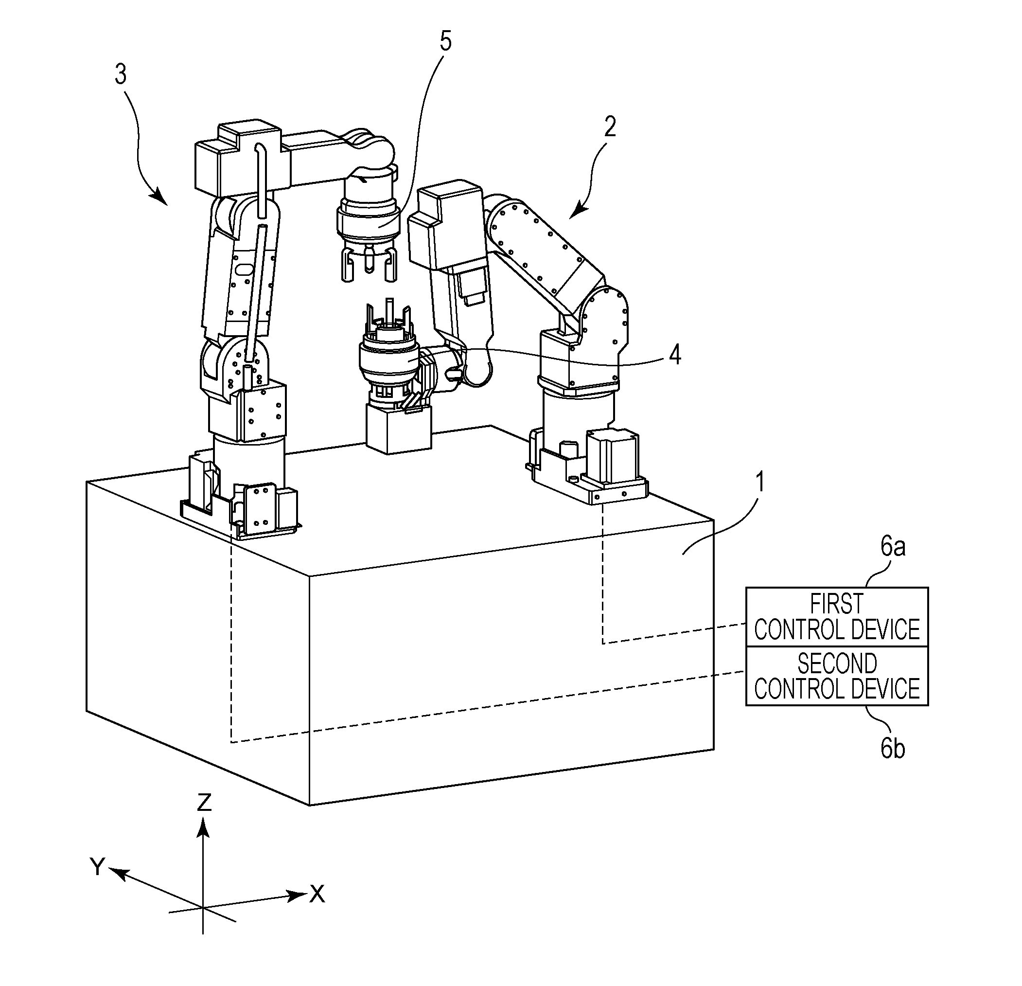
[0024]FIG. 1 is a perspective view of assembly equipment according to a first embodiment. Referring to FIG. 1, a first robot arm 2 and a second robot arm 3 of a six-axis articulated type are arranged on a base 1 to oppose each other. At distal ends of the first robot arm 2 and the second robot arm 3, holding hands 4 and 5 are provided. Each of the holding hands 4 and 5 comprises an attachment having a force sensor mounted in a wrist portion of the robot arm and an aligning holding mechanism provided in a rotation mechanism. The force sensor can detect the force applied to the hand during assembly. The force sensor does not always need to be mounted, but can be mounted according to user's need.

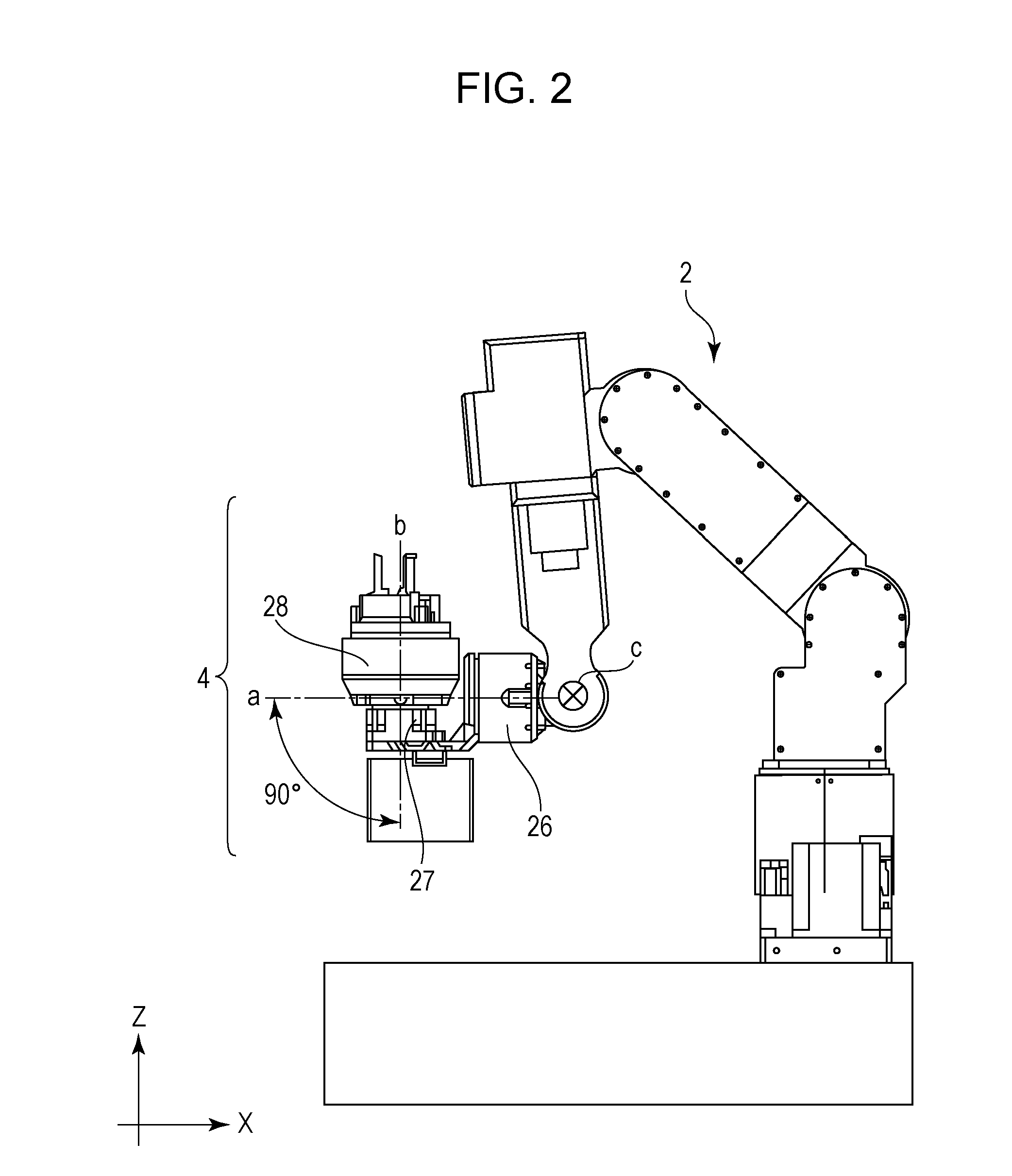
[0025]FIG. 2 illustrates the first holding hand 4 in the first embodiment. As illustrated in FIG. 2, an attachment 26 comprises a mechanism that rotates about a rotation shaft a. The attachment 26 further comprises a rotation mechanism 27 having a rotation shaft b. The rotation shaft b intersec...

second embodiment

[0042]FIG. 3 illustrates a second embodiment. Referring to FIG. 3, a working unit 30 is installed in the assembly equipment of the first embodiment. The working unit 30 performs a special assembly operation requested by the user, such as screwing and application of various coating materials. The working unit 30 comprises a working section 31 that performs assembly operation, for example, a screwdriver or a coating device.

[0043]Here, a detailed description will be given of a case in which the working unit 30 comprises a coating device for ejecting a coating material. Hereinafter, the working section 31 will be referred to as a coating device. The coating device stores various coating materials necessary for assembly such as adhesive, grease, and self-adhesive, and performs assembly while applying a predetermined amount of coating material onto a predetermined position of a part to be assembled.

[0044]First, the assembly equipment conveys an annular part, which is aligned and held by a...

third embodiment

[0052]FIG. 4 illustrates a third embodiment. Referring to FIG. 4, a workpiece supply pallet 42 is set on a workpiece supply table 41 in a working area of a first holding hand 4, and a plurality of annular workpieces 43 are placed on the workpiece supply pallet 42. Further, a parts supply pallet 52 is set on a parts supply table 51 in a working area of a second holding hand 5, and a plurality of sub-pallets are placed on the parts supply pallet 52. A plurality of annular parts 53 of one type are stacked on each of the sub-pallets.

[0053]FIG. 6 illustrates working areas of the holding hand 4 and 5 provided in robot arms according to the third embodiment. In an overlapping area of a working area α of the first holding hand 4 and a working area β of the second holding hand 5, a cooperative working area 60 where the two robot arms perform assembly in cooperation with each other is provided.

[0054]Operation performed in the third embodiment will be described in detail below.

[0055]As illustr...


PUM


Abstract

Assembly equipment comprises a base, a first holding hand provided in a first robot arm set on the base, a second holding hand provided in a second robot arm set on the base, and a control device configured to control the first and second robot arms and the first and second holding hands. The first holding hand comprises an attachment connected to the first robot arm and having a rotation shaft, and an aligning holding mechanism provided in a rotation mechanism having a rotation shaft located to intersect the rotation shaft of the attachment or located in a skewed positional relationship with the rotation shaft of the attachment. A cooperative working area of the first and second holding hands is provided in an overlapping area where working areas of the first and second holding hands overlap with each other.

Description

BACKGROUND OF THE INVENTION[0001]1. Field of the Invention[0002]Aspects of the present invention generally relate to assembly equipment that performs assembly operation with two robot arms having aligning holding hands.[0003]2. Description of the Related Art[0004]In industry, a number of pieces of assembly equipment that perform assembly operation using robot arms have been used. In recent years, there has been a demand for assembly equipment that achieves assembly operation using robot arms, instead of manually performing assembly operation. In contrast, in manual assembly performed in production factories, a human cell production system has been introduced in which conveyors are removed and a person directly conveys workpieces and assembles a plurality of kinds of parts and complementary materials to the workpieces.[0005]There is a new cell production system called a “machine cell production system” that enhances productivity of an operator by combining manpower and assembly equip...

Claims


Application Information

Patent Timeline
IPC IPC(8): B23Q1/00
CPCB23Q1/00B25J9/0084Y10T29/53991B25J9/0096B25J17/025B25J9/0087B23P19/04
Inventor OSATO, TOSHIAKIARAI, TAKASHIHIRASAWA, SHUICHI
Owner CANON KK
Why Eureka
Try Eureka