Spur-
pruning produces a relatively greater yield in consistent growing conditions over the season but can result in low yield or quality where conditions are variable or the grape variety is generally low-yielding.
For example, frosts may result in poor growth on the closest spurs to the
trunk while summer drought may result in poor growth on the outer spurs later in the season.
Moreover, stripping-out may also be hazardous when canes are ripped free of the
vine as they may whip the person in the face and eyes.
These processes are also done manually and while trimming is generally unskilled, wrapping requires skilled labour.
Thus,
cane-pruning of grapevines is a labour-intensive process that has a number of sub-processes requiring skilled workers.
In contrast,
cane-pruning leaves unwanted canes wrapped about the fruiting wire and thus the
cutting techniques of the spur-pruning machines may
cut the fruiting wire and / or may not adequately remove the canes.
While a number of machines have been developed to alleviate the heavy manual requirement of spur-pruning grapevines, there has been little development in machines for
cane-pruning given the high-skill requirement.
Typical prior art electrical wire strippers are also unsuitable as they cannot be used to strip
cut canes of grapevines, other organic material or any intrinsically irregular material that grows on the line.
It is inherently difficult to ensure that all of the material on the line is stripped as electrical wire strippers rely on the material and line being fixed in position and dimensions, or alternatively rely on the wire stripper blades moving to accommodate any irregularity.
While the Langlois
machine offers a mechanical alternative to manual stripping of the canes, there are a number of problems that may arise in operation.
For example:the rollers must be lifted over each post along the row of vines thereby reducing speed and efficiency;the rotating rollers rip the canes from the wire with substantial force, thereby potentially damaging any uncut canes or detaching the fruiting wire from the posts;the stripped canes are ejected upwards in the Langlois device at substantial speed, and these may land on the
tractor, personnel, other vines or otherwise prove undesirable;the canes are required to extend above the wire to be effectively stripped which means conventional “pre-pruning” or “summer” pruning must be reduced.
Typical prior art wire strippers are also unsuitable as they cannot be used to strip
cut canes of grapevines, other organic material or any intrinsically irregular material that grows on the line.
It is inherently difficult to ensure that all of the material on the line is stripped as the prior art wire strippers rely on the material and line being fixed in position and dimensions, or alternatively rely on the wire stripper blades moving to accommodate any irregularity.
While this arrangement provides optimal growing conditions it presents a problem for pruning and stripping operations.
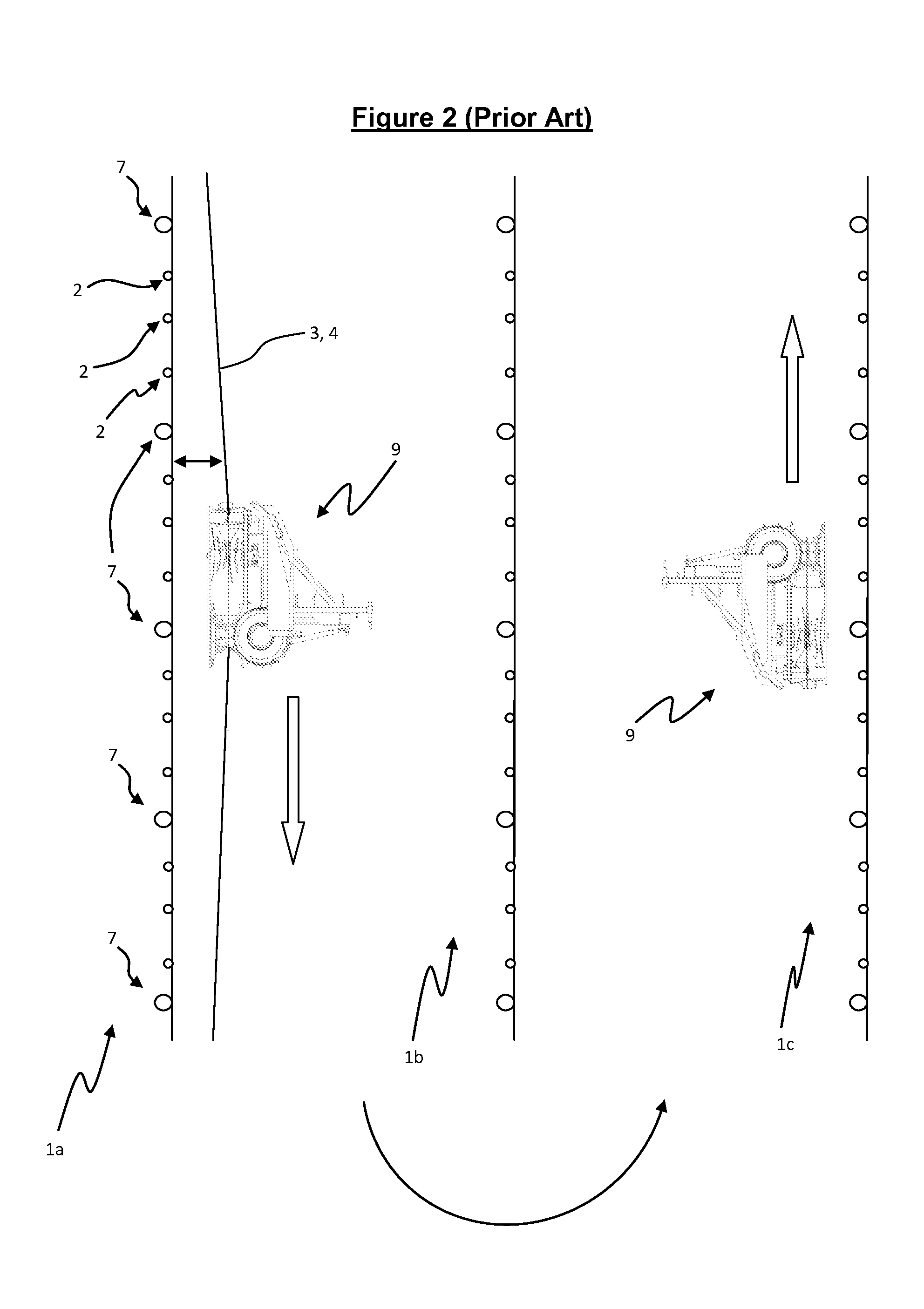
However, once the apparatus has completed a row the carrier cannot simply turn down the next row as the apparatus will be on the opposite side of the carrier to the trellis
system to be stripped.
Another solution, albeit complex and inconvenient, is to construct the stripping apparatus with the carrier mounting and drive connector on both sides of the apparatus so that it can be disconnected and re-mounted on either side of the carrier at the end of each row.
However, it will be obvious that disconnecting the apparatus would normally take longer and present more difficulty than simply driving back to the start of the next row.
It will be appreciated that such prior art methods either duplicate the cost of the stripping apparatus or increase the time and fuel costs for operation of a single stripping apparatus.
Some vineyards include
vine-rows that extend over undulating ground which results in loosening tension on the wire when detached from the posts and / or where the vertical tension of the wires reverses over their length.
This reversed tension presents problems for the George et al.
machine if the tension is directed toward away from the line guide as the wires may exit the line guide and be cut by the surrounding blades.
Similarly, where the
wire tension is too loose the wire may bend around the line guide, exit and become entangled in the blades and be damaged.
Further problems arise where the wire is made from steel that is too soft as narrow and restrictive channels may abrade the steel.
The prior art may also not be able to accommodate more than one wire at a time which is important for effectively stripping material.
However, in many applications, the material is only loosely wrapped about the wire and thus there is potential for any stripping mechanism contacting the loose material to push the loose material along the wire without stripping it.
Moreover, in combined stripping and mulching devices the loose material may drop off the wire before being mulched.
These operations result in larger, harder canes wrapped about the wires which are correspondingly harder to remove and using manual labour to remove such canes can be prohibitively expensive.
These operations therefore leave the canes on the lifting wires for the useful life of the
plant and then the entire
plant and wire
system are removed and new vines planted, obviously at great expense.

