Coupling Unit and Battery Module comprising an Integrated Pulse Width Modulation Inverter and Cell Modules that can be Replaced During Operation

a technology of pulse width modulation and coupling unit, which is applied in the direction of cell structure combination, electric vehicle, electric device, etc., can solve the problems of price, size and reliability disadvantages, and achieve the effect of increasing the service life of the battery and reducing the exten

Inactive Publication Date: 2013-08-08
SAMSUNG SDI CO LTD +1
View PDF4 Cites 11 Cited by
  • Summary
  • Abstract
  • Description
  • Claims
  • Application Information

AI Technical Summary

Benefits of technology

[0015]The control unit can also be designed to connect all the first inputs of the coupling units of a selected battery module line to the first outputs of the coupling units of the selected battery module line and all the second inputs of the coupling units of a selected battery module line to the second outputs of the coupling units of the selected battery module line at a first time, and to decouple all the first and second inputs of the coupling units of the selected battery module line from the first and second outputs of the coupling units of the selected battery module line and to connect the first and second outputs of the coupling units of the selected battery module line at a second time. As a result, the full output voltage of the selected battery module line is provided at the output of the battery module line at the first time, while a voltage of 0 V is output at the second time. As a result, the coupling units of the battery module line are operated as a pulse-controlled inverter which, as shown in FIG. 1, connects either the positive pole or the negative pole of the DC voltage intermediate circuit to the outputs of the pulse-controlled inverter. By virtue of using, for example, a pulse-width-modulated actuation means, an approximately sinusoidal output voltage can be generated in this way, with the motor windings of the drive motor acting as filters. The battery of the invention can therefore completely take on the function of the pulse-controlled inverter of the prior art. In an embodiment with a plurality of battery module lines, each battery module line can generate an output voltage, the phase of said output voltage being shifted in relation to the other battery module lines, so that a drive motor can be directly connected to the battery. In this case, it is additionally advantageous for the total capacitance of the battery to be distributed between a plurality of battery module lines, as a result of which parallel connection of battery cells can be dispensed with or can be performed at least to a considerably lower extent. As a result, compensation currents between battery cells which are connected in parallel are eliminated or at least reduced, this increasing the service life of the battery. Instead of a single DC voltage intermediate circuit as in FIG. 1, the number of DC voltage intermediate circuits provided is therefore equal to the number of battery module lines. This provides the advantage that any buffer capacitors which may be provided can be of smaller dimensions or can be completely dispensed with.

Problems solved by technology

However, a changeover switch can usually be realized only as an electromechanical switch, this being associated with disadvantages in respect of price, size and reliability.

Method used


Image

  • Coupling Unit and Battery Module comprising an Integrated Pulse Width Modulation Inverter and Cell Modules that can be Replaced During Operation
  • Coupling Unit and Battery Module comprising an Integrated Pulse Width Modulation Inverter and Cell Modules that can be Replaced During Operation
  • Coupling Unit and Battery Module comprising an Integrated Pulse Width Modulation Inverter and Cell Modules that can be Replaced During Operation

Examples


first embodiment

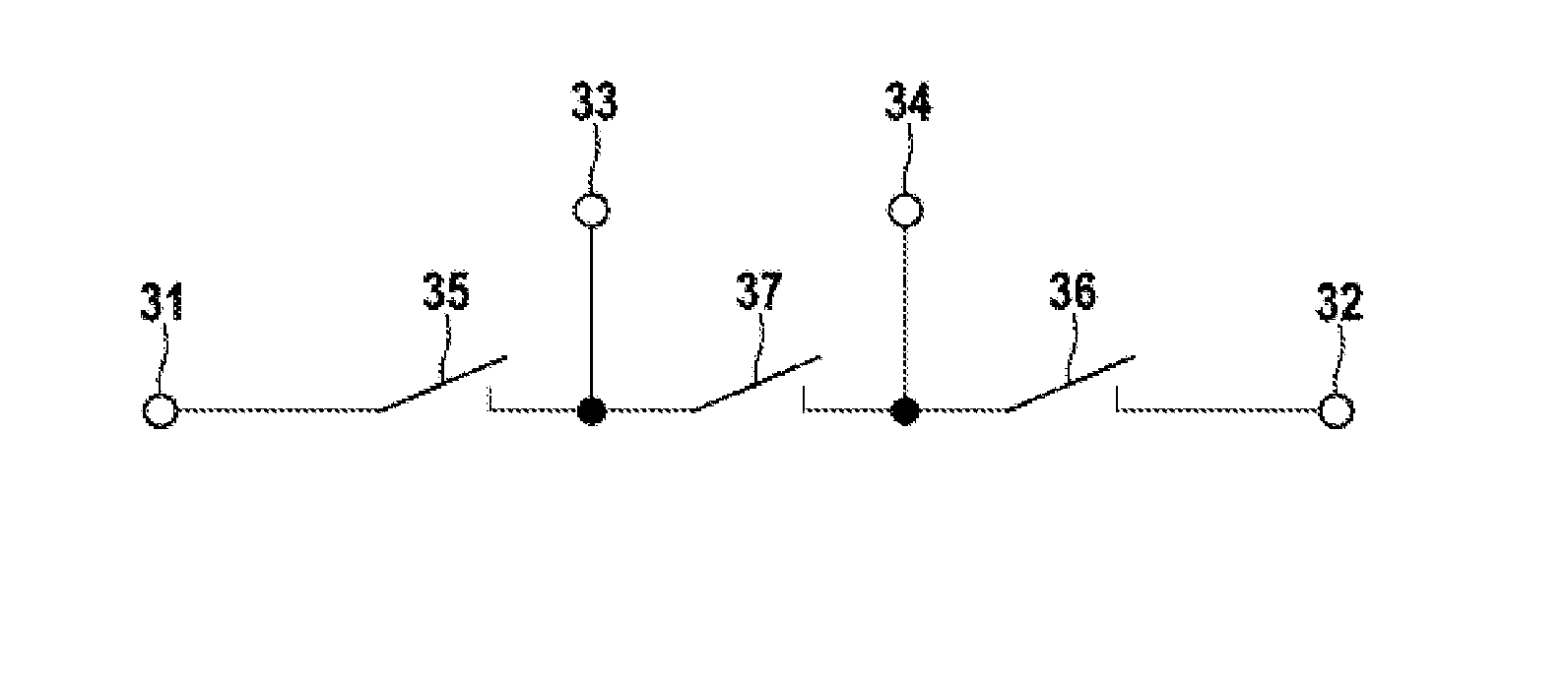
[0028]FIG. 4 shows the coupling unit 30 in which a first, a second and a third switch 35, 36 and 37 are provided. The first switch 35 is connected between the first input 31 and the first output 33, the second switch is connected between the second input 32 and the second output 34, and the third switch is connected between the first output 33 and the second output 34. This embodiment provides the advantage that the switches 35, 36 and 37 can be implemented in a simple manner as semiconductor switches, for example MOSFETs or IGBTs. Semiconductor switches have the advantage of a favorable price and a high switching speed, and therefore the coupling unit 30 can react to a control signal or a change in the control signal within a short time and high changeover rates can be achieved.

second embodiment

[0029]FIG. 5 shows the coupling unit 30 which has a first changeover switch 38 and a second changeover switch 39. Embodiments in which only one of the two changeover switches 38, 39 is provided and the other is replaced by the switches 35 and 37 or 37 and 36 are also feasible. The changeover switches 38, 39 have the principal property of being able to connect only one of their respective inputs to their output, while the respectively remaining input is decoupled. This provides the advantage that the first input 31 of the coupling unit 30 can never be connected to the second input 32 of the coupling unit 30, and therefore the connected battery cells can never be short-circuited, even in the event of a malfunction in the switches or control unit used. The changeover switches 38 and 39 can be realized as electromechanical switches in a particularly simple manner.

[0030]FIG. 6 shows an embodiment of the battery module 40 according to the invention. A plurality of battery cells 41 is conn...


PUM


Abstract

A coupling unit for a battery module, includes a first input, a second input, a first output and a second output. The coupling unit is configured to connect the first input to the first output and the second input to the second output, on a first control signal, and, on a second control signal, to separate the first input from the first output and the second input from the second output, and to connect the first output to the second output.

Description

[0001]The present invention relates to a coupling unit for a battery module and a battery module having a coupling unit of this kind.PRIOR ART[0002]It has become apparent that, in the future, battery systems will be increasingly used, both in stationary applications and in vehicles such as hybrid and electric vehicles. In order to be able to meet the requirements in respect of voltage and available power given for a respective application, a large number of battery cells are connected in series. Since the current provided by a battery of this kind has to flow through all the battery cells and a battery cell can conduct only a limited current, additional battery cells are often connected in parallel in order to increase the maximum current. This can be done either by providing a plurality of cell windings within a battery cell housing or by externally interconnecting battery cells. However, one problem in this case is that compensation currents between the battery cells which are con...

Claims


Application Information

Patent Timeline
Patent Type & Authority Applications(United States)
IPC IPC(8): H02J7/00B60L11/18H02J1/00
CPCH01M10/0525Y02T10/7061H01M10/5004H01M10/5016H01M10/5061H02J7/022H02M7/483H02M7/49Y02T10/7011B60L11/1864B60L2270/42B60L11/1851H02J1/00H02J7/0063Y02T10/7005H01M10/425H01M10/625H01M10/613H01M10/656B60L15/007B60L58/18B60L58/21H02J7/02H02J2207/20Y02E60/10Y02T10/64Y02T10/70
Inventor BUTZMANN, STEFANFINK, HOLGER
Owner SAMSUNG SDI CO LTD
Why Eureka
Try Eureka