Methods for forming a connection with a micromachined ultrasonic transducer, and associated apparatuses

a micro-machined ultrasonic transducer and connection method technology, applied in ultrasonic/sonic/infrasonic diagnostics, mechanical vibration separation, instruments, etc., can solve the problem of difficult to bend the larger amount of signal interconnection, difficult to implement arrangement, and difficulty in interconnection with individual pmut devices

Active Publication Date: 2013-08-08
RES TRIANGLE INST
View PDF6 Cites 14 Cited by
  • Summary
  • Abstract
  • Description
  • Claims
  • Application Information

AI Technical Summary

Benefits of technology

[0014]Aspects of the present disclosure thus address the identified needs and provide other advantages as otherwise detailed herein.

Problems solved by technology

However, for a forward-looking transducer array in a relatively small catheter / endoscope, such an arrangement may be difficult to implement due to the severe bend requirement for the flex cable (i.e., about 90 degrees) in order for the transducer array to be disposed within the lumen of the relatively small catheter / endoscope.
Moreover, for a forward-looking two-dimensional (2D) transducer array, signal interconnection with the individual pMUT devices may also be difficult.
However, as the number of wires and / or flex cable assemblies increases, the more difficult it becomes to bend the larger amount of signal interconnections about the ends of the transducer device to achieve the 90 degree bend required to integrate the transducer array into a catheter / endoscope.
Accordingly, such limitations may undesirably limit the minimum size (i.e., diameter) of the catheter / endoscope that can readily be achieved.

Method used


Image

  • Methods for forming a connection with a micromachined ultrasonic transducer, and associated apparatuses
  • Methods for forming a connection with a micromachined ultrasonic transducer, and associated apparatuses
  • Methods for forming a connection with a micromachined ultrasonic transducer, and associated apparatuses

Examples


Embodiment Construction

[0023]The present disclosure now will be described more fully hereinafter with reference to the accompanying drawings, in which some, but not all aspects of the disclosure are shown. Indeed, the disclosure may be embodied in many different forms and should not be construed as being limited to the aspects set forth herein; rather, these aspects are provided so that this disclosure will satisfy applicable legal requirements. Like numbers refer to like elements throughout.

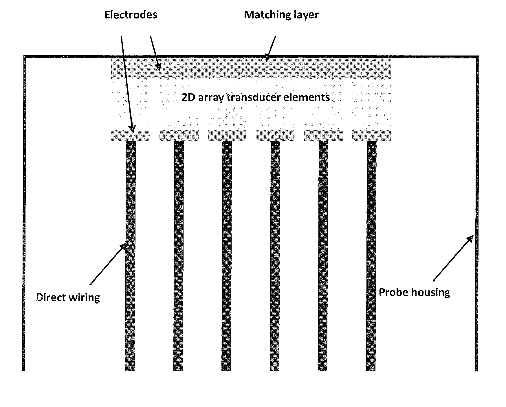
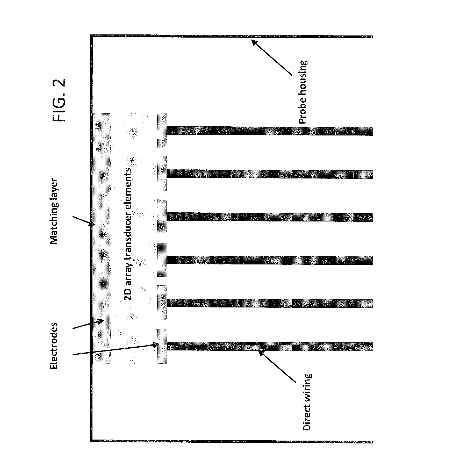
[0024]Aspects of the present disclosure are generally applicable to ultrasonic transducers, though particular aspects are particularly directed to a piezoelectric micromachined ultrasound transducer (“pMUT”) having an air-backed cavity. More particularly, aspects of the present disclosure are directed to improved methods of forming an electrically-conductive connection between a pMUT device and, for example, an integrated circuit (“IC”), a flex cable, or a cable assembly, whereby individual signal leads extend paralle...


PUM

PropertyMeasurementUnit
diameteraaaaaaaaaa
diameteraaaaaaaaaa
diameteraaaaaaaaaa

Abstract

A method and associated apparatus directed to a piezoelectric micromachined ultrasonic transducer (pMUT) defining an air-backed cavity are provided. A first via defined by a device substrate and associated dielectric layer, and extending to the first electrode, is substantially filled with a first conductive material. A support member engaged with the device substrate defines a second via extending to the first conductive material. The second via has a second conductive material disposed thereon, forms an electrically-conductive engagement with the first conductive material, and extends outwardly of the second via to be accessible externally to the support member. A connective element extends through a third via defined by a connection support substrate and is in electrically-conductive engagement with the second conductive material, wherein one of the connective element and connection support substrate is bonded to one of the support member and second conductive material by a bonding material engaged therebetween.

Description

BACKGROUND OF THE DISCLOSURE[0001]1. Field of the Disclosure[0002]Aspects of the present disclosure relate to ultrasonic transducers, and, more particularly, to methods of forming a connection with a piezoelectric micromachined ultrasonic transducer defining an air-backed cavity, and associated apparatuses.[0003]2. Description of Related Art[0004]Some micromachined ultrasonic transducers (MUTs) may be configured, for example, as a piezoelectric micromachined ultrasonic transducer (pMUT) as disclosed in U.S. Pat. No. 7,449,821 assigned to Research Triangle Institute, also the assignee of the present disclosure, which is also incorporated herein in its entirety by reference.[0005]The formation of pMUT device, such as the pMUT device defining an air-backed cavity as disclosed in U.S. Pat. No. 7,449,821, may involve the formation of an electrically-conductive connection between the first electrode (i.e., the bottom electrode) of the transducer device, wherein the first electrode is disp...

Claims


Application Information

Patent Timeline
Patent Type & Authority Applications(United States)
IPC IPC(8): H01L41/332H01L41/047
CPCB06B1/0622G10K11/002H01L41/0475H01L41/29Y10T29/42A61B8/4494H01L41/332H01L41/0973A61B8/4444H10N30/875H10N30/2047H10N30/06B06B1/06G10K11/00H10N30/87H10N30/082
Inventor DAUSCH, DAVIDCARLSON, JIMSANDERS, CHRISTOPHER BREWERGOODWIN, SCOTT H.
Owner RES TRIANGLE INST
Why Eureka
Try Eureka