Charge control method and discharge control method for electric storage apparatus

a technology of electric storage apparatus and control method, which is applied in the direction of parallel/serial switching, transportation and packaging, and the arrangement of several simultaneous batteries, etc., can solve the problems of reducing charge efficiency, heat loss increases, and electrostatic capacity errors of capacitors, so as to prevent overcharge, reduce heat loss, and suppress voltage variations of capacitors. the effect of inter-terminal voltag

Active Publication Date: 2013-08-08
YOSHIFUMI TAKEDA
View PDF2 Cites 27 Cited by
  • Summary
  • Abstract
  • Description
  • Claims
  • Application Information

AI Technical Summary

Benefits of technology

[0050]With a charge control method and a discharge control method for an electric storage apparatus according to the present invention, among the capacitors constituting an electric storage unit, pairs of adjacent capacitors are sequentially connected in parallel, whereby the inter-terminal voltages of the capacitors are equalized, and as a result, variations in the inter-terminal voltages of the capacitors can be suppressed. This eliminates the need for a parallel monitor for preventing overcharge at the time of charging, whereby heat loss does not occur and thus charge efficiency improves. Also, at the time of discharging, the discharge time can be increased.

Problems solved by technology

If charging is continued, the capacitors having a smaller electrostatic capacity are overcharged, causing a degradation, or in the worst case, a breakage.
Furthermore, actual capacitors have electrostatic capacity errors and differences in self discharge characteristics, and thus the inter-terminal voltage varies from capacitor to capacitor.
As a result, heat loss occurs due to the resistance of the parallel monitor, reducing charge efficiency.
That is, with the conventional charge control method disclosed in Patent Document 1, there are very large variations in the inter-terminal voltage of the capacitors between the blocks, and the parallel monitor requires a long operation time to prevent overcharge, and thus heat loss increases and as a result charge efficiency is reduced.

Method used


Image

  • Charge control method and discharge control method for electric storage apparatus
  • Charge control method and discharge control method for electric storage apparatus
  • Charge control method and discharge control method for electric storage apparatus

Examples


embodiment 1

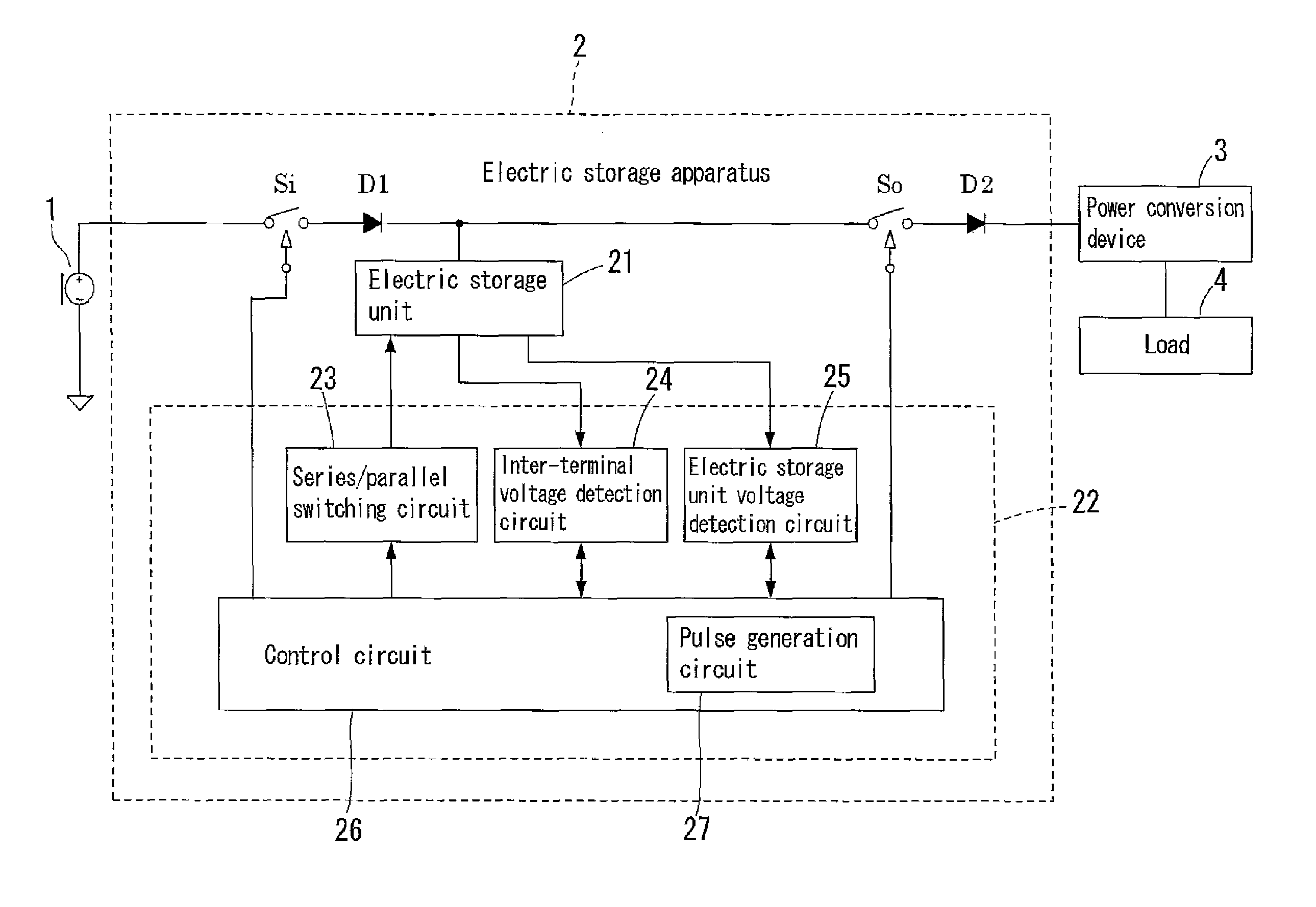
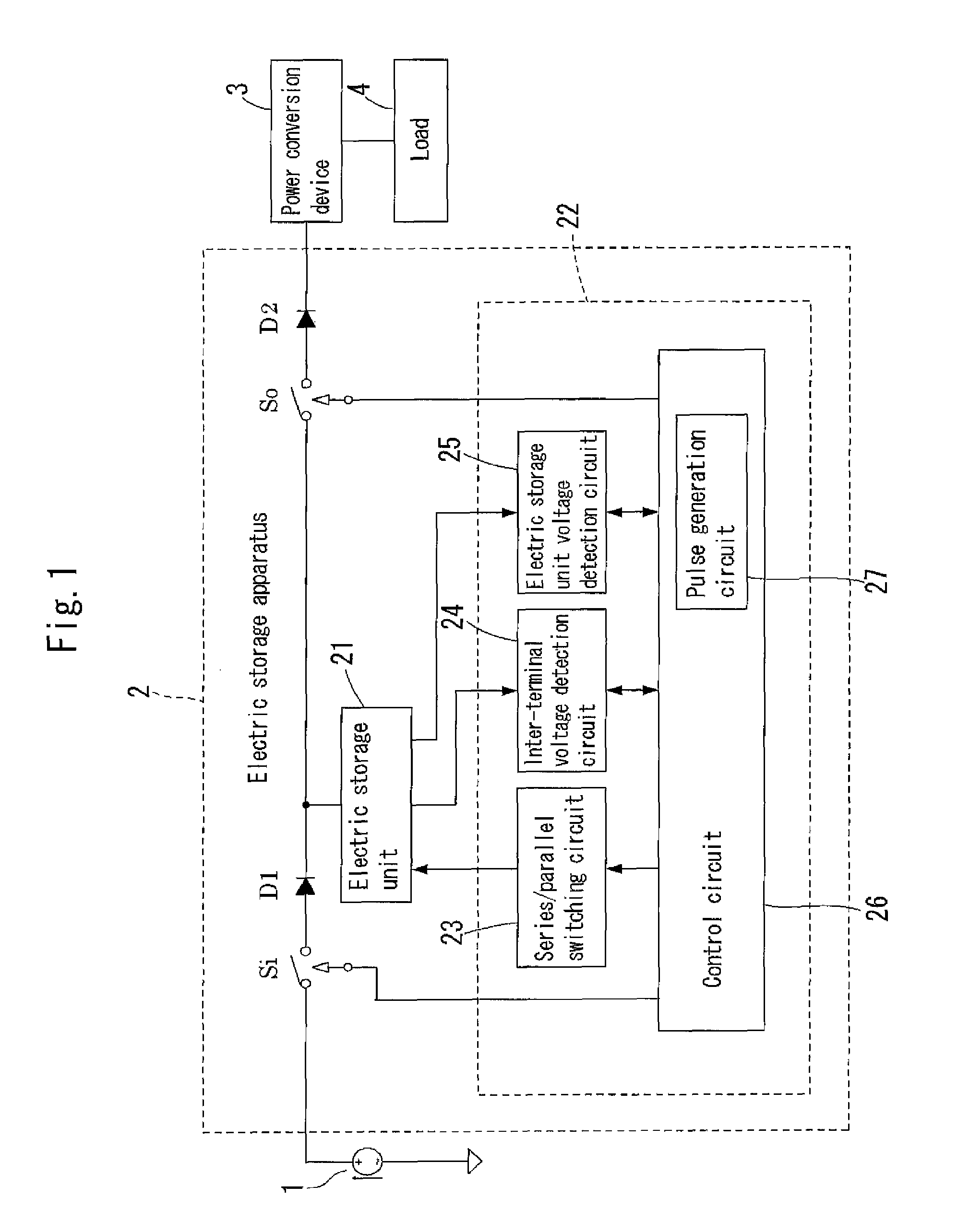
[0082]FIG. 1 shows a configuration of a power supply system including an electric storage apparatus. In the present embodiment, a charge control method carried out by an electric storage apparatus 2 shown in FIG. 1 will now be described. The electric storage apparatus 2 stores direct current power supplied from a direct current power source 1, and the direct current power is converted to alternating current power by a power conversion device 3 and thereafter supplied to a load 4, or the direct current power is directly supplied to the load 4.

[0083]It is desirable that the direct current power source 1 is a current source. As the direct current power source 1, for example, a solar cell or the like can be used. It is also possible to use other power supply sources such as a wind power generator and an engine power generator. Such power supply sources, however, include alternating current power supply sources and direct current power supply sources, and thus if an alternating current p...

embodiment 2

[0198]In the present embodiment, a discharge control method according to the present invention will be described. The electric storage apparatus 2 and the electric storage unit 21 used for discharge control have the same configurations as those of Embodiment 1.

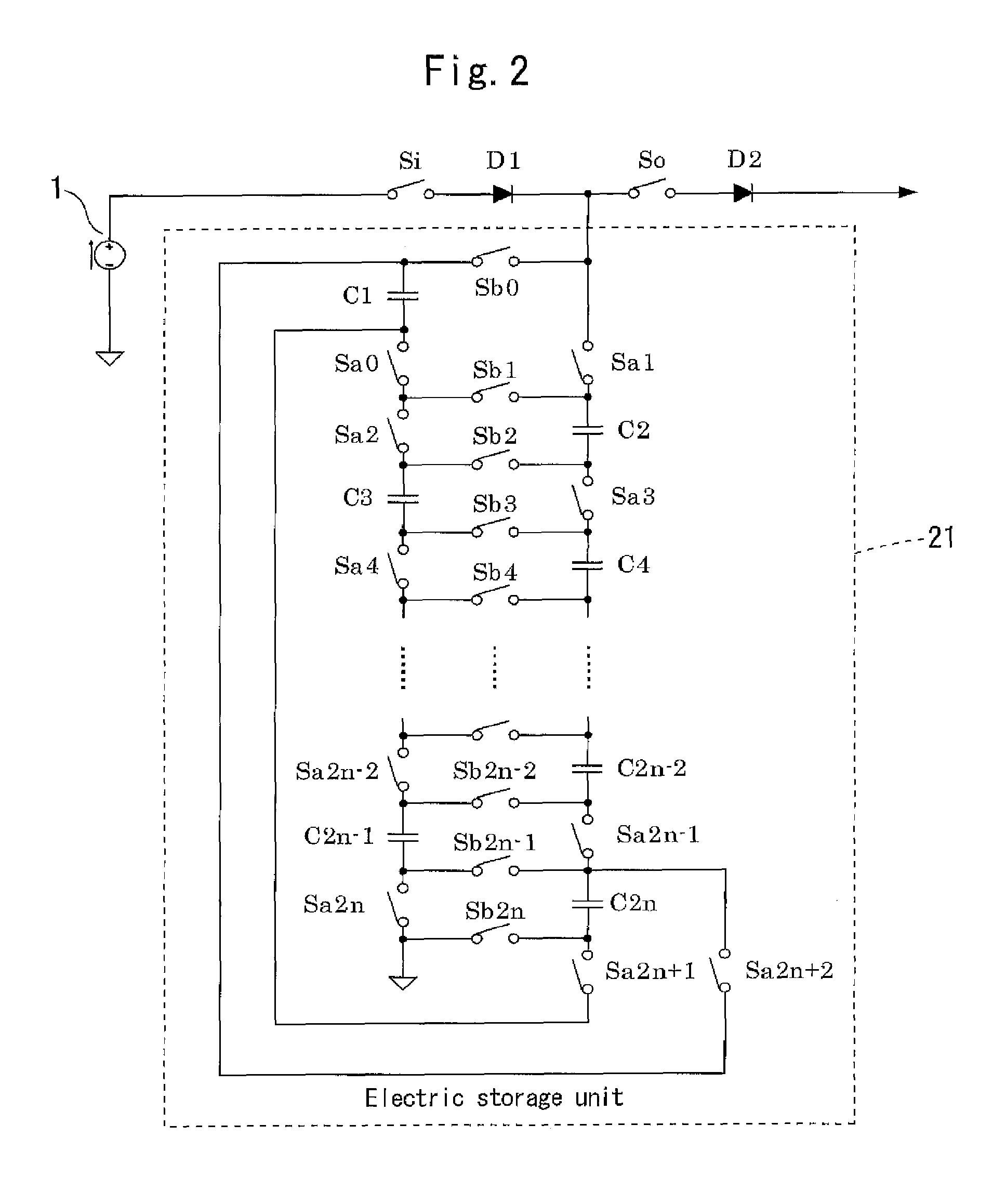
[0199]A feature of the discharge control method of the present invention is that if, in an electric storage unit implemented with 2n capacitors, a unit in which two adjacent capacitors are connected in parallel is denoted by a parallel section, the following first processing and second processing are repeated from a state in which the number P of parallel sections is n until all capacitors are connected in series.

[0200](1) When the number P of parallel sections is 1 or greater, i is an integer whose value cycles from 1 to 2n, kj (j is an integer that satisfies 1≦j≦P) is P 0s or any even numbers, satisfying 0≦kj≦2n−2, while a value corresponding to i is increased by one every time a predetermined period of time passes, a connec...

embodiment 3

[0222]The present embodiment will discuss a combination of a charge control method and a discharge control method according to the present invention, or in other words, a case where discharging is performed while charging is performed. FIG. 19 is a flowchart for carrying out a combination of a charge control method and a discharge control method according to the present invention.

[0223]Note that FIG. 19 is a flowchart in the case where power for charge is larger than power for discharge. In the diagram, the same reference numerals are given to steps that are the same as those of FIGS. 17 and 18. Hereinafter, the flowchart of FIG. 19 will be described, focusing on steps that are different from the flowcharts of FIGS. 17 and 18.

[0224]Control is started from a state in which all capacitors Ci (i=1, 2, . . . , 2n) are in a fully discharged state, or in other words, a state in which the capacitors Ci are connected in series (the number P of parallel sections=0) (step S11, S12, S13). Then...


PUM


Abstract

According to the charge control method of the present invention, as an electric storage means, a group of capacitors is used that include 2n (where n is an integer of 2 or more) electric double layer capacitors, from first to 2n-th electric double layer capacitors, having an equal electrostatic capacity, and that is configured such that adjacent electric double layer capacitors are connected either in series or in parallel by a switch and the 2n-th electric double layer capacitor and the first electric double layer capacitor are connected in parallel by a switch. Among the 2n capacitors Ci constituting the electric storage unit 21, adjacent capacitors are sequentially switched from a series connection to a parallel connection, or the 2n-th capacitor C2n and the first capacitor C1 are switched to a parallel connection state, whereby variations in the inter-terminal voltages of the capacitors are suppressed.

Description

TECHNICAL FIELD[0001]The present invention relates to a charge control method and a discharge control method for an electric storage apparatus in which electric double layer capacitors are used as an electric storage device.BACKGROUND ART[0002]Electric double layer capacitors, which have features of long cycle life and a wide working temperature range, are attracting attention as a new type of electric storage device that can replace secondary batteries.[0003]A power supply system will be described in which electric double layer capacitors (hereinafter also referred to simply as “capacitors”) are used as an electric storage device, with reference to FIG. 23.[0004]Direct current power supplied from a direct current power source 1 such as a solar cell is temporarily stored in an electric storage unit 21 implemented with a plurality of capacitors in an electric storage apparatus 2. Unlike secondary batteries, with capacitors, the inter-terminal voltage varies significantly in proportio...

Claims


Application Information

Patent Timeline
Patent Type & Authority Applications(United States)
IPC IPC(8): H02J7/00H02J7/02
CPCH02J7/0024H02M3/07H02J7/34H02J7/0068H02J7/00
Inventor TAKEDA, HARUMITAKEDA, YOSHIFUMI
Owner YOSHIFUMI TAKEDA
Why Eureka
Try Eureka