Microwave frequency tunable filtering balun
a filtering balun and microwave technology, applied in the field of microwave communication, can solve the problem that relatively little research has been done on the tunable balun, and achieve the effect of increasing the depressing depth and reducing the magnitude loss
- Summary
- Abstract
- Description
- Claims
- Application Information
AI Technical Summary
Benefits of technology
Problems solved by technology
Method used
Image
Examples
first embodiment
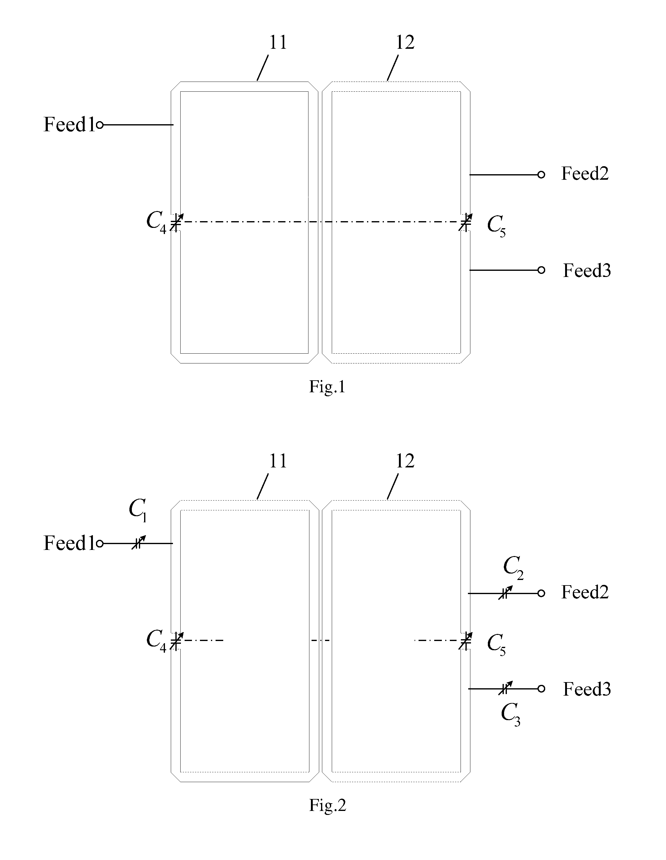
[0023]As shown in FIG. 1, in microwave frequency tunable filtering balun according to present invention, the microwave frequency tunable filtering balun comprises a first microwave split ring transmission line resonator 11 and a second microwave split ring transmission line resonator 12, a fourth variable capacitor C4 and a fifth variable capacitor C5. Wherein, the first microwave split ring transmission line resonator 11 and second microwave split ring transmission line resonator 12 are arranged in a bilaterally symmetrical manner. The fourth variable capacitor C4 and fifth variable capacitor C5 have same parameters, and the capacitances of the fourth variable capacitor C4 and fifth variable capacitor C5 are defined as Cv. The first microwave split ring transmission line resonator 11 and the second microwave split ring transmission line resonator 12 are vertically symmetrical about a central line (as shown in FIG. 1). It should be noted that, in present embodiment, the first microw...
second embodiment
[0024]As shown in FIG. 2, the microwave frequency tunable filtering balun according to present invention is similar as that one shown in FIG. 1 and comprises a first microwave split ring transmission line resonator 11 and a second microwave split ring transmission line resonator 12, a fourth variable capacitor C4, a fifth variable capacitor C5, unbalanced input port Feed1, first balanced output port Feed2 and second balanced output port Feed3. Accordingly, such similar structures are not introduced in detail for conciseness. Now, only the difference between the embodiments in FIG. 1 and FIG. 2 is illustrated. The microwave frequency tunable filtering balun shown in FIG. 2 further comprises a first variable capacitor C1, a second variable capacitor C2 and a third variable capacitor C3. The first terminal of the first variable capacitor C1 is connected to the unbalanced input port Feed1, and the second terminal of the first variable capacitor C1 is connected to the upper portion of th...
third embodiment
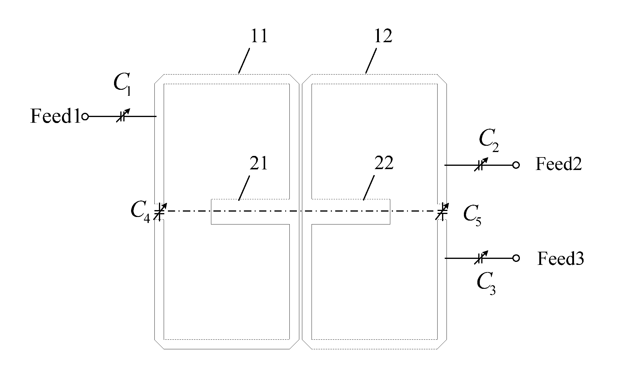
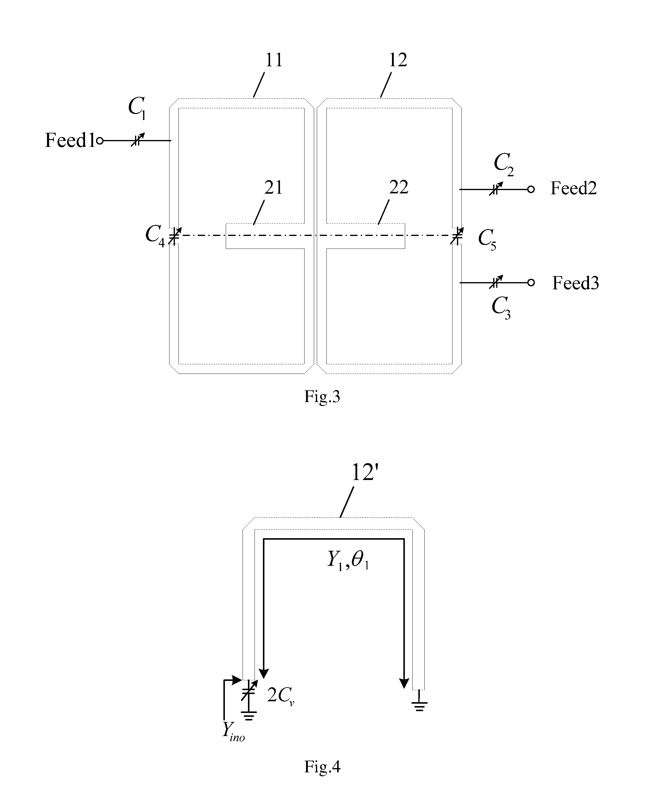
[0025]As shown in FIG. 3, the microwave frequency tunable filtering balun according to present invention is similar as that one shown in FIG. 2 and comprises a first microwave split ring transmission line resonator 11 and a second microwave split ring transmission line resonator 12, a first variable capacitor C1, a second variable capacitor C2, a third variable capacitor C3, a fourth variable capacitor C4, a fifth variable capacitor C5, unbalanced input port Feed1, first balanced output port Feed2 and second balanced output port Feed3. Accordingly, such similar structures are not introduced in detail for conciseness. Now, only the difference between the embodiments in FIG. 2 and FIG. 3 is illustrated. The microwave frequency tunable filtering balun shown in FIG. 3 further comprises a first open-circuited microwave transmission line 21 arranged at the middle of the first microwave split ring transmission line resonator 11 in a vertically symmetrical manner about the central line and ...
PUM
 Abstract
Description
Claims
Application Information
 - R&D
- Intellectual Property
- Life Sciences
- Materials
- Tech Scout
- Unparalleled Data Quality
- Higher Quality Content
- 60% Fewer Hallucinations
Browse by: Latest US Patents, China's latest patents, Technical Efficacy Thesaurus, Application Domain, Technology Topic, Popular Technical Reports.
© 2025 PatSnap. All rights reserved.Legal|Privacy policy|Modern Slavery Act Transparency Statement|Sitemap|About US| Contact US: help@patsnap.com


