
Method and apparatus for generating a reference signal sequence in a wireless communication system

a reference signal and wireless communication technology, applied in the field of wireless communication, can solve the problems of fading generation, deterioration of channel estimation performance, and increase in cell planning complexity

Active Publication Date: 2013-08-08
LG ELECTRONICS INC
View PDF3 Cites 46 Cited by
  • Summary
  • Abstract
  • Description
  • Claims
  • Application Information

AI Technical Summary

Benefits of technology

The patent provides a method and apparatus for generating a reference signal sequence in a wireless communication system. The method involves receiving a cell-specific sequence hopping parameter and a UE-specific sequence group hopping parameter from a base station, and generating a reference signal sequence based on the parameters. This allows for the simultaneous transmission of multiple reference signals without interference or collision, ensuring orthogonality between user equipments. The length of the reference signal sequence is larger than six times the size of a resource block, and it may be generated by shifting the base sequence cyclically. The use of the reference signals for demodulation of signals can improve the overall performance of the wireless communication system.

Problems solved by technology

In wireless communication system environments, fading is generated because of multi-path time latency.
If the method of assigning the reference signal between data subcarriers is used, the performance of channel estimation can be deteriorated because the density of reference signals is low.
If the OCC is applied together while performing sequence hopping on reference signals that the plurality of user equipments with different bandwidths transmits, the complexity of cell planning increases.
In other words, it is difficult to guarantee the orthogonality between the reference signals that the plurality of user equipments transmits.

Method used

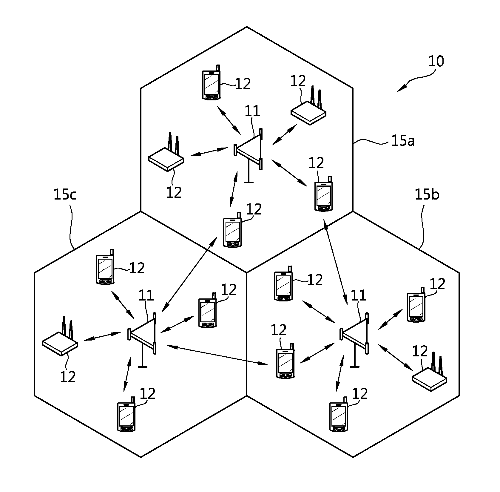
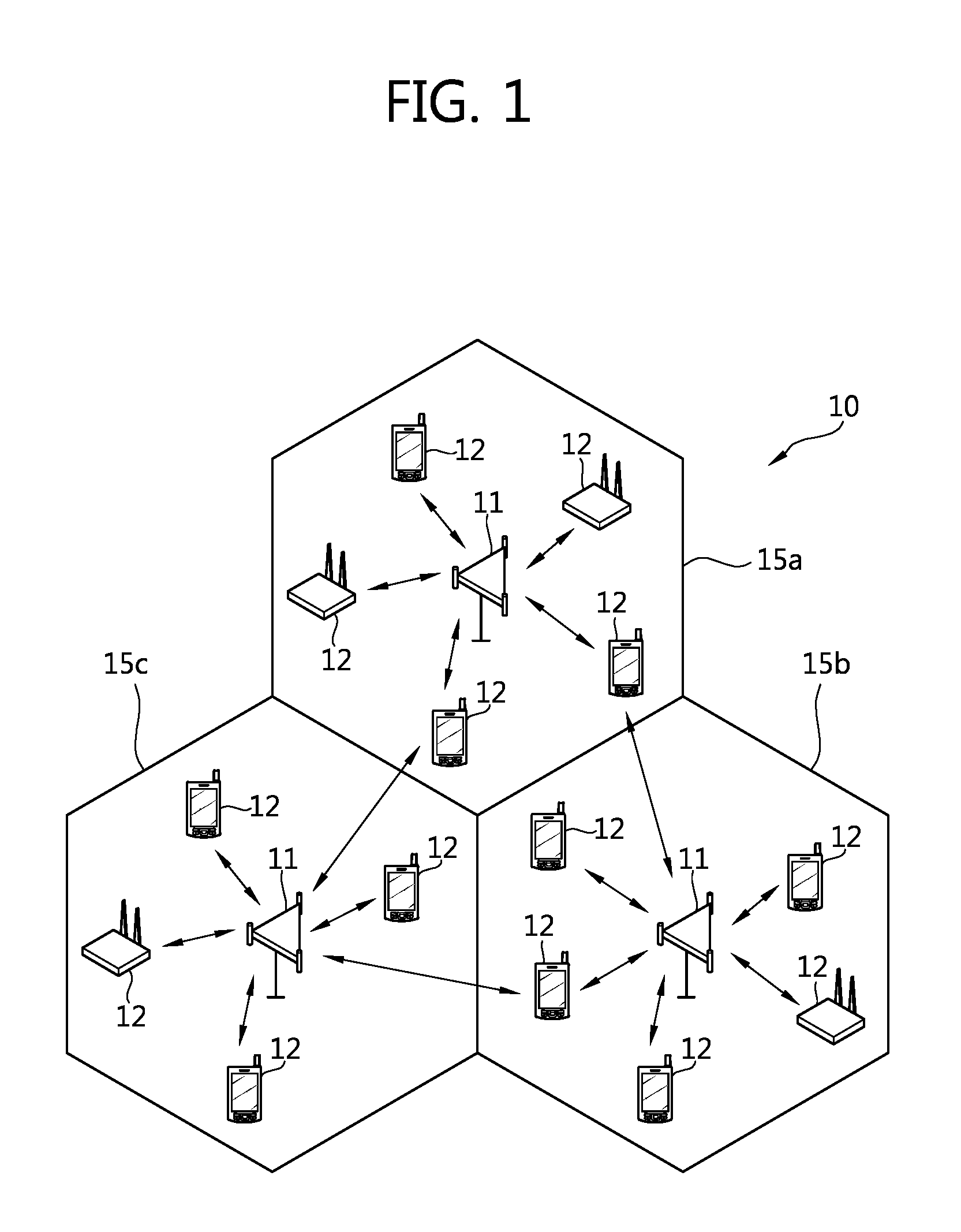
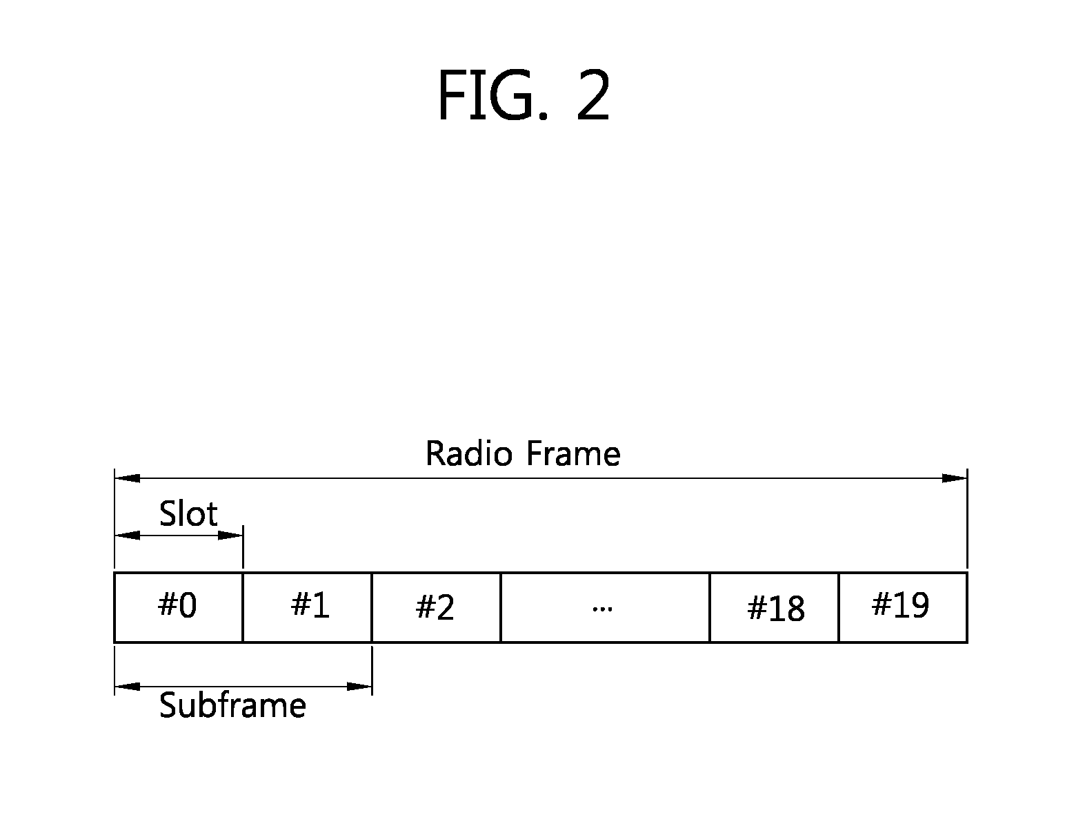

Image

  • Method and apparatus for generating a reference signal sequence in a wireless communication system
  • Method and apparatus for generating a reference signal sequence in a wireless communication system
  • Method and apparatus for generating a reference signal sequence in a wireless communication system

Examples


Embodiment Construction

[0044]The following technique may be used for various wireless communication systems such as code division multiple access (CDMA), a frequency division multiple access (FDMA), time division multiple access (TDMA), orthogonal frequency division multiple access (OFDMA), single carrier-frequency division multiple access (SC-FDMA), and the like. The CDMA may be implemented as a radio technology such as universal terrestrial radio access (UTRA) or CDMA2000. The TDMA may be implemented as a radio technology such as a global system for mobile communications (GSM) / general packet radio service (GPRS) / enhanced data rates for GSM evolution (EDGE). The OFDMA may be implemented by a radio technology such as institute of electrical and electronics engineers (IEEE) 802.11 (Wi-Fi), IEEE 802.16 (WiMAX), IEEE 802.20, E-UTRA (evolved UTRA), and the like. IEEE 802.16m, an evolution of IEEE 802.16e, provides backward compatibility with a system based on IEEE 802.16e. The UTRA is part of a universal mobi...


PUM


Abstract

The present invention relates to a method and apparatus for generating a reference signal sequence in a wireless communication system. User equipment receives a cell-specific sequence hopping parameter from a base station, receives, from the base station, a user equipment (UE)-specific sequence group hopping (SGH) parameter which is specific to said user equipment, and generates a reference signal sequence on the basis of a base sequence number of a base sequence, wherein the base sequence number is determined for each slot on the basis of the cell-specific sequence hopping parameter and of the use equipment-specific sequence group hopping parameter. Here, the determination of whether or not to apply sequence hopping to the base sequence number indicated by the user equipment-specific sequence group hopping parameter overrides that of whether or not to apply sequence hopping to the base sequence number indicated by the cell-specific sequence hopping parameter.

Description

BACKGROUND OF THE INVENTION[0001]1. Field of the Invention[0002]The present invention relates to a wireless communication and, more particularly, to a method and an apparatus for generating a reference signal sequence in a wireless communication system.[0003]2. Related Art[0004]Multiple-input multiple-output (MIMO) technology can be used to improve the efficiency of data transmission and reception using multiple transmission antennas and multiple reception antennas. MIMO technology may include a space frequency block code (SFBC), a space time block code (STBC), a cyclic delay diversity (CDD), a frequency switched transmit diversity (FSTD), a time switched transmit diversity (TSTD), a precoding vector switching (PVS), spatial multiplexing (SM) for implementing diversity. An MIMO channel matrix according to the number of reception antennas and the number of transmission antennas can be decomposed into a number of independent channels. Each of the independent channels is called a layer...

Claims


Application Information

Patent Timeline
Patent Type & Authority Applications(United States)
IPC IPC(8): H04J13/00
CPCH04J11/005H04L5/0007H04J13/0074H04W28/18H04W48/16H04L27/2613H04L5/0026H04L5/0037H04L5/0082H04L5/0092H04L5/0012H04J11/003H04L5/0051H04B7/0452H04L5/0048
Inventor NOH, MIN SEOKCHUNG, JAE HOONKO, HYUN SOOHAN, SEUNG HEELEE, MOON IL
Owner LG ELECTRONICS INC
Learn More