
Thermal solar absorber system generating heat and electricity

a solar energy and absorber technology, applied in solar heating energy, space heating and ventilation, domestic heating details, etc., can solve the problems of lack of power adequacy, lack of value creation to end-users, and the present state of solar energy systems that suffer from the effects of solar energy, so as to prevent overheating

Inactive Publication Date: 2013-08-15
INNOGIE
View PDF10 Cites 25 Cited by
  • Summary
  • Abstract
  • Description
  • Claims
  • Application Information

AI Technical Summary

Benefits of technology

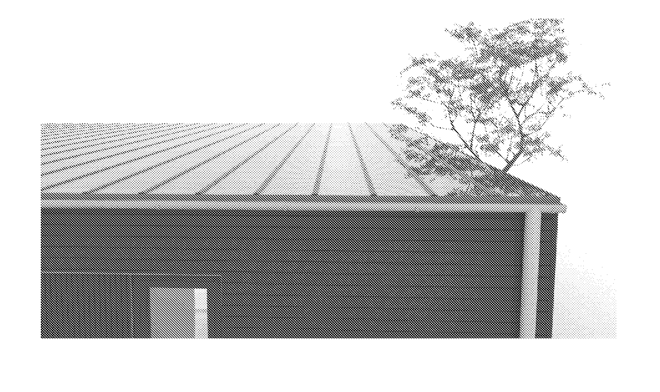
The solar power system described in this patent is designed using low-cost components and can provide energy for a normal household in a Nordic climate throughout the year. The system has an intelligent controller that can control its operation and improve its efficiency compared to existing systems. It can incorporate sensors to sense its current operating conditions and predict future operating conditions, allowing for timely operational changes to improve energy efficiency. Additionally, the system can provide heat, hot water, and electricity to the household while maintaining its appearance as a normal house.

Problems solved by technology

A factor in favour of solar thermal systems is that unlike other renewable energy systems, it is considered a proven and tested technology by consumers, but still lack to prove value creation to the end-users.
However, the present state of systems based on solar energy appear to suffer from one or more drawbacks such as lack of power adequacy, poor design and poor profitability.
Usually, this leads to a decrease in the value of the house simply from the fact that people do not find current solutions aesthetically attractive.
The photovoltaic technology transforms certain spectrums of the solar radiation into electricity and the rest into heat, which in this regard is considered as loss.

Method used


Image

  • Thermal solar absorber system generating heat and electricity
  • Thermal solar absorber system generating heat and electricity
  • Thermal solar absorber system generating heat and electricity

Examples


Embodiment Construction

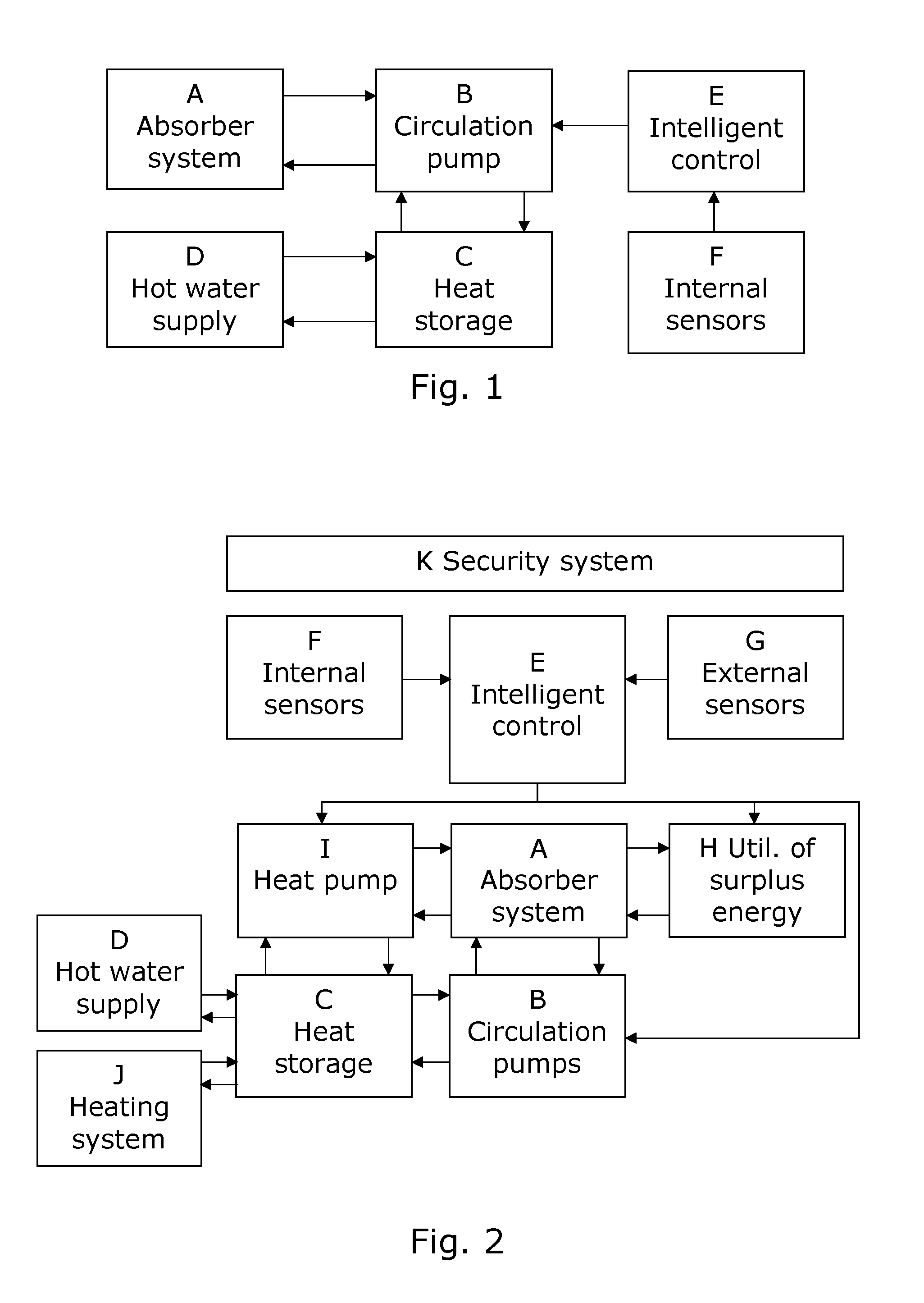
[0057]FIG. 1 shows elements of a system where an absorber system A with a thermal solar absorber is connected with a circulation system comprising a circulation pump B controlled by an intelligent controller E taking input from one or more internal sensors F. The circulation system B circulates the absorber liquid, e.g.

[0058]through a heat exchanger, to a heat storage C which is connected to a hot water supply D. Given input from the sensors F, the intelligent controller E runs a control algorithm serving to optimize utilization of the energy provided by the absorber system A by controlling valves and circulation pumps B to circulate the absorber liquid so as to deliver energy to hot water supply D, if required, or to the heat storage C as.

[0059]FIG. 2 illustrates a more detailed diagram of a preferred embodiment. Apart from the elements A-F already described and shown in FIG. 1, the system comprises external sensors G generating inputs to the intelligent controller E, a system for ...


PUM


Abstract

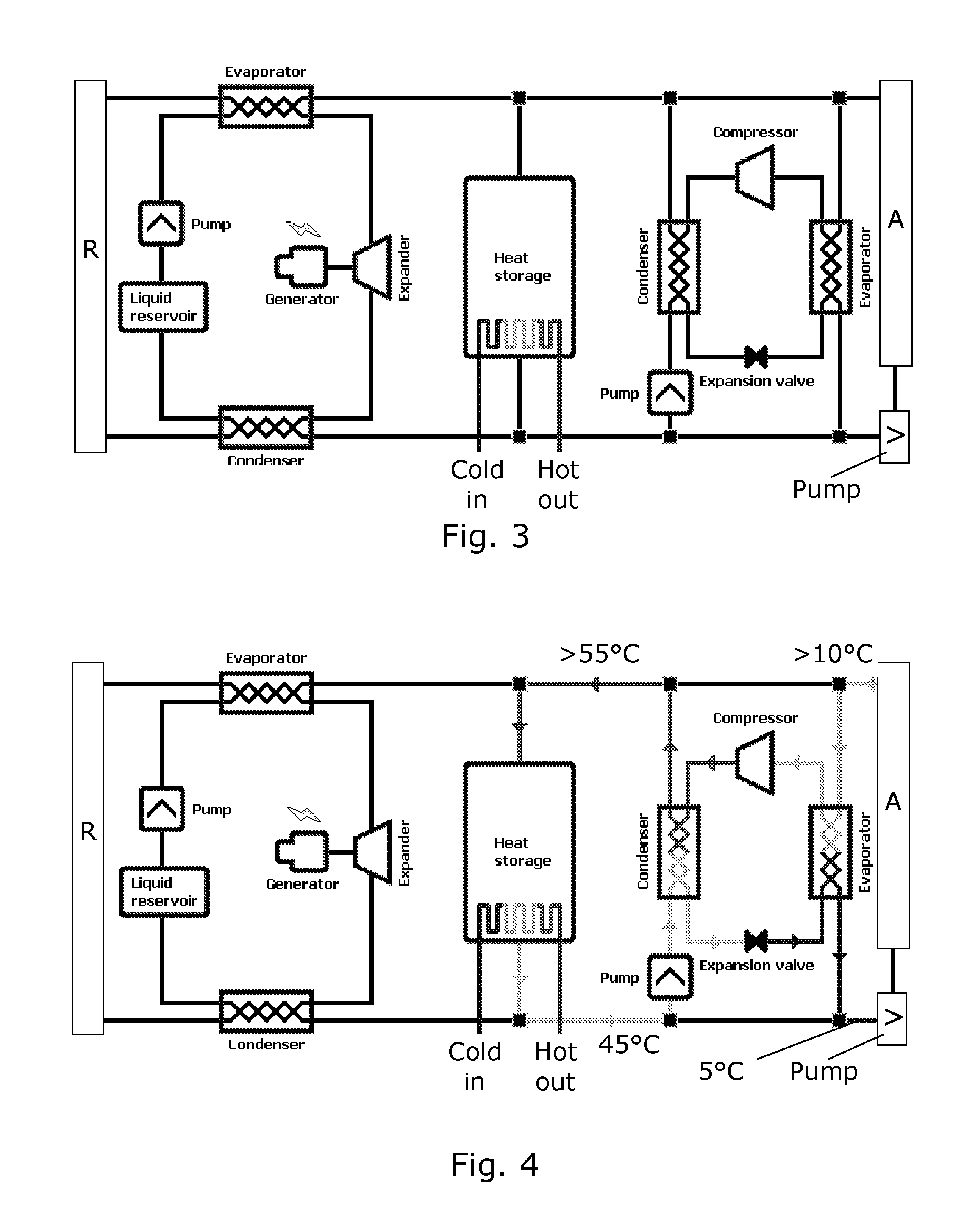
The invention provides a solar power system for use as a solar roofing concept based on an absorber system with a solar thermal absorber and a circulation system for circulating absorber liquid through the absorber and a core system which extracts energy from the absorber liquid and provides hot water to a building. An intelligent controller uses data about external conditions to control the core system, where both current conditions and predicted conditions are taken into account. In preferred embodiments, the system can generate heat, hot water and electric energy to cover the need for a normal household. When excess heat is generated, the thermal energy can be used by an organic Rankine cycle (ORC) machine for electricity production. A forecasting and control unit using external weather measurements in combination with internet weather forecasts will by fuzzy logic calculate the optimum periods of time for use of the heat pump during the colder periods. Preferably, the intelligent controller can switch between 15 different modes of operation of the system to optimized energy efficiency to match the actual working conditions. In embodiments, the system includes a geothermal hose also connected to the liquid system of the absorber system, thus providing a synergetic exchange of energy with the solar absorber

Description

FIELD OF THE INVENTION[0001]The invention relates to the field of solar power, especially systems for using solar power for heating hot water for a household, heating houses and delivering electricity for a house. The solution according to the invention show how a solar absorber can be fully integrated into a roofing solution and how a number of related technologies can ensure an intelligent operation yielding the advantages described above.BACKGROUND OF THE INVENTION[0002]Alternative sources of energy have been investigated and utilized to some extend for many years. However the fast increasing awareness of the change of the global climate has put an extreme focus onto developing and utilizing new and more effective sources of energy. More and more international conferences deal with solutions for the looming climate problem that the world is facing. Green technologies can provide solutions to the challenges posed by the climate changes.[0003]A factor in favour of solar thermal sys...

Claims


Application Information

Patent Timeline
Patent Type & Authority Applications(United States)
IPC IPC(8): F03G6/00F25B27/00F24J2/04F24S10/50F24S10/75
CPCF24J2/045Y02B10/40F24J2/4621F24J3/081F24J2002/502Y02B10/20F03G6/005F03G7/04F24D19/1042F24D19/1045F24H2250/00Y02E10/44Y02B10/70Y02E10/46Y02E10/12F03G6/003F25B27/002F24J2/268F24T10/10F24S10/755F24S40/50F24S2080/502F24S20/67Y02A30/00Y02E10/10F24H15/242F24H15/414F24H15/335F24H15/136F24H15/128F24H15/262F24H15/20F03G6/004F03G4/035
Inventor HANSEN, KRISTIAN HARLEY
Owner INNOGIE
Learn More