Plasma processing apparatus

Active Publication Date: 2013-08-15
TOKYO ELECTRON LTD
View PDF11 Cites 15 Cited by
  • Summary
  • Abstract
  • Description
  • Claims
  • Application Information

AI Technical Summary

Benefits of technology

The present invention is a plasma processing apparatus that includes an upper electrode and a lower electrode and is capable of preventing electric discharge even when a higher DC voltage is applied to the upper electrode compared to a conventional case. The invention is based on the finding that when the distance between the electrodes is increased, the voltage that generates electric discharge is increased. The apparatus includes a bent portion and / or a barrier portion to increase the resistance between the gas supply opening and the gas diffusion room, thereby preventing linear electric discharge. The technical effect of the invention is to prevent electric discharge caused by applying a DC voltage from occurring.

Problems solved by technology

Further, if the length of the gas flow path is increased, a pressure loss of the processing gas in the gas flow path is also increased.

Method used


Image

  • Plasma processing apparatus
  • Plasma processing apparatus
  • Plasma processing apparatus

Examples


Embodiment Construction

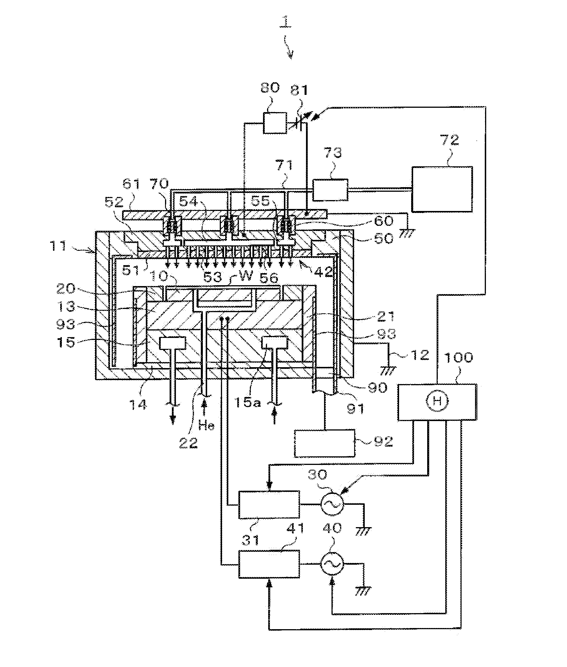
[0033]Hereinafter, illustrative embodiments will be described with reference to the accompanying drawings. FIG. 1 is a longitudinal cross sectional view schematically illustrating a configuration of a plasma processing apparatus 1 in accordance with an illustrative embodiment. The plasma processing apparatus 1 in accordance with the present illustrative embodiment is, for example, a parallel plate type plasma etching apparatus.

[0034]The plasma processing apparatus 1 includes a substantially cylindrical processing chamber 11 in which a wafer chuck 10 configured to hold a wafer W as a silicon substrate is provided. The processing chamber 11 is electrically connected and grounded to a ground line 12. Within the wafer chuck 10, an electrode (not illustrated) is provided and the wafer W can be attracted to and held on the wafer chuck 10 by an electrostatic force generated by applying a DC voltage to the electrode.

[0035]A lower surface of the wafer chuck 10 is supported on a susceptor 13 ...


PUM

PropertyMeasurementUnit
Flow rateaaaaaaaaaa
Electric potential / voltageaaaaaaaaaa

Abstract

A plasma processing apparatus comprises an upper electrode 42, a lower electrode, a grounding member 61 provided above the upper electrode 42 via an insulating member 60; and a DC power supply for applying a DC voltage to the upper electrode 42. Gas diffusion rooms 54 and 55 communicating with a gas supply opening 53 formed at a lower surface of the upper electrode 42 are formed in the upper electrode 42 and a gas flow path 62 communicating with the gas diffusion rooms 54 and 55 is formed in the insulating member 60. A bent portion 63 for allowing a gas within the gas flow path to flow in a direction having at least a horizontal component is formed at the gas flow path 62 such that an end of the gas flow path 62 cannot be seen from the other end thereof when viewed from the top.

Description

CROSS-REFERENCE TO RELATED APPLICATION[0001]This application claims the benefit of Japanese Patent Application No. 2012-010445 filed on Jan. 20, 2012, and U.S. Provisional Application Ser. No. 61 / 592,688 filed on Jan. 31, 2012, the entire disclosures of which are incorporated herein by reference.FIELD OF THE INVENTION[0002]The present disclosure relates to a plasma processing apparatus that performs a plasma process on a target object.BACKGROUND OF THE INVENTION[0003]A parallel plate type (capacitively coupled) plasma processing apparatus, an inductively coupled plasma processing apparatus, a microwave plasma processing apparatus or the like has been widely used for performing a microprocess such as an etching process or a film forming process on a target object such as a semiconductor wafer (hereinafter, referred to as “wafer”) by plasma.[0004]Particularly, in the parallel plate type plasma processing apparatus, a high frequency power is applied to at least one of an upper electrod...

Claims


Application Information

Patent Timeline
IPC IPC(8): H05H1/46
CPCH05H1/46H01J37/32449C23C16/503C23C16/50H01J37/32568H01J37/32807H01J37/3244H01J37/32541H01L21/3065
Inventor TANAKA, KIYOSHI
Owner TOKYO ELECTRON LTD
Why Eureka
Try Eureka