Method and system for estimating electrical angular speed of a permanent magnet machine

a technology of permanent magnet machines and electrical angular speed, applied in the direction of motor/generator/converter stoppers, dynamo-electric converter control, dynamo-electric gear control, etc., can solve the problem that the existing techniques for estimating the speed of permanent magnet machines are insufficien

Active Publication Date: 2013-08-15
GM GLOBAL TECH OPERATIONS LLC
View PDF6 Cites 16 Cited by
  • Summary
  • Abstract
  • Description
  • Claims
  • Application Information

AI Technical Summary

Benefits of technology

[0023]In accordance with the disclosed embodiments, methods, systems and apparatus are provided for estimating angular velocity (and / or angular position) of a rotor of a permanent magnet machine (PMM). These improved methods, systems and apparatus allow for angular velocity (and / or position) of the rotor to be estimated without having to wait for the system to settle to a steady state value, for example, during a transient phase of a three-phase short operating mode when a short-circuit fault response is applied at an inverter module.

Problems solved by technology

Existing techniques for estimating speed of permanent magnet machine can be inadequate since it is necessary to wait for the system to settle from a transient response phase to a steady state phase before an estimate can be computed.

Method used


Image

  • Method and system for estimating electrical angular speed of a permanent magnet machine
  • Method and system for estimating electrical angular speed of a permanent magnet machine
  • Method and system for estimating electrical angular speed of a permanent magnet machine

Examples


Embodiment Construction

[0040]As used herein, the word “exemplary” means “serving as an example, instance, or illustration.” The following detailed description is merely exemplary in nature and is not intended to limit the invention or the application and uses of the invention. Any embodiment described herein as “exemplary” is not necessarily to be construed as preferred or advantageous over other embodiments. All of the embodiments described in this Detailed Description are exemplary embodiments provided to enable persons skilled in the art to make or use the invention and not to limit the scope of the invention which is defined by the claims. Furthermore, there is no intention to be bound by any expressed or implied theory presented in the preceding technical field, background, brief summary or the following detailed description.

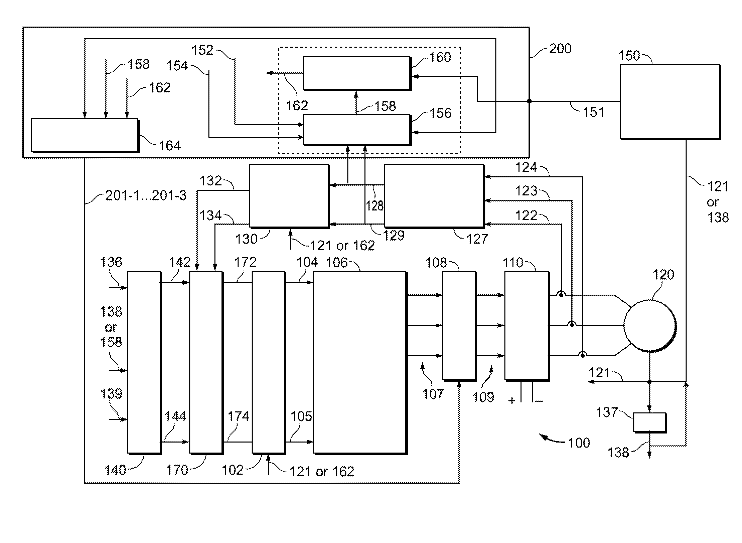
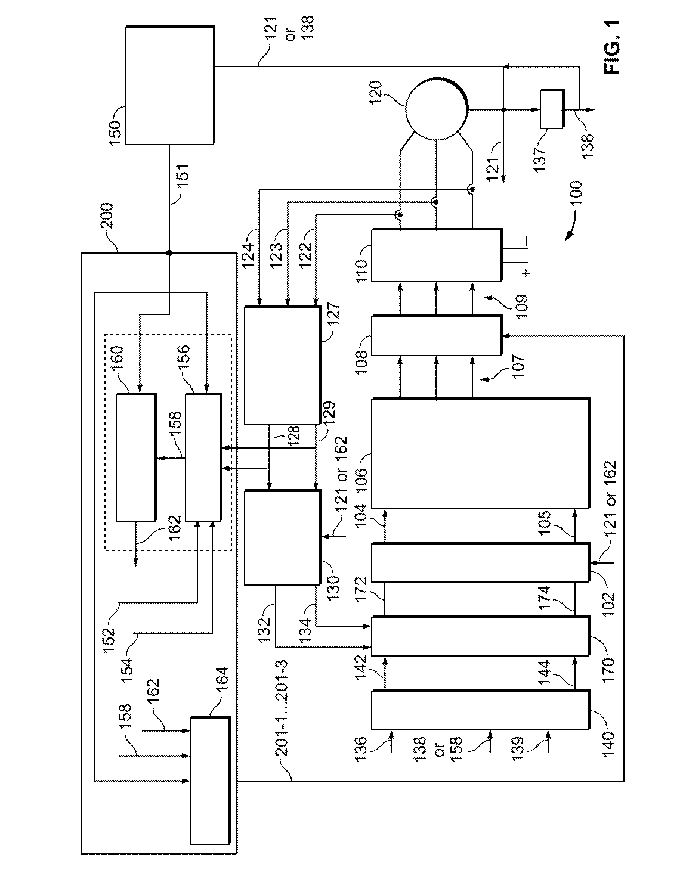
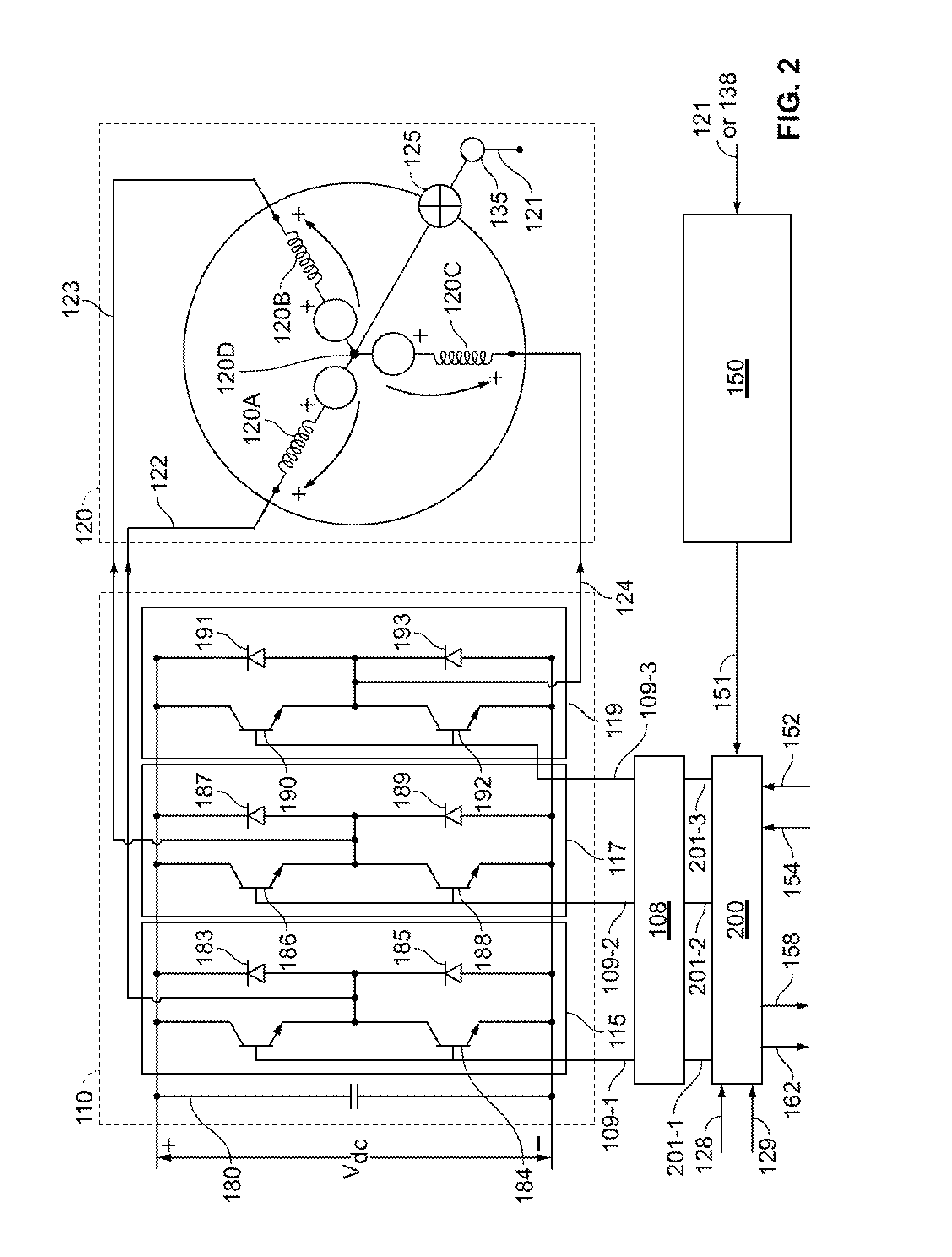
[0041]Before describing in detail embodiments that are in accordance with the present invention, it should be observed that the embodiments reside primarily in combinations of me...


PUM


Abstract

Methods, systems and apparatus are provided for estimating electrical angular speed of a permanent magnet machine based on two-phase stationary reference frame feedback stator current samples, and a dimensionless gain (K) that is computed based on a sampling time (T) and machine parameters.

Description

TECHNICAL FIELD[0001]The present invention generally relates to electric machines. More specifically, the present invention relates to estimating electrical angular speed of a permanent magnet machine.BACKGROUND OF THE INVENTION[0002]In recent years, advances in technology, as well as ever evolving tastes in style, have led to substantial changes in the design of automobiles. One of the changes involves the complexity of the electrical and drive systems within automobiles, particularly alternative fuel vehicles, such as hybrid, electric, and fuel cell vehicles. Such alternative fuel vehicles typically use an electric motor, perhaps in combination with another actuator, to drive the wheels.[0003]Hybrid and electric vehicles (HEVs) typically include an electric traction drive system that includes at least one alternating current (AC) electric motor which is driven by a power inverter module (PIM) with power from a direct current (DC) power source, such as a storage battery. Motor wind...

Claims


Application Information

Patent Timeline
Patent Type & Authority Applications(United States)
IPC IPC(8): H02P21/12
CPCH02P21/146H02P21/0039H02P21/18H02P21/24
Inventor PERISIC, MILUNSON, YO CHANGALLEGOS-LOPEZ, GABRIELHITI, SILVA
Owner GM GLOBAL TECH OPERATIONS LLC
Why Eureka
Try Eureka