

Image display apparatus
a technology of image display and display screen, which is applied in the field of image display apparatuses, can solve the problem of inability to adjust the white balan
- Summary
- Abstract
- Description
- Claims
- Application Information
AI Technical Summary
Benefits of technology
Problems solved by technology
Method used
Image

Examples
embodiment 1
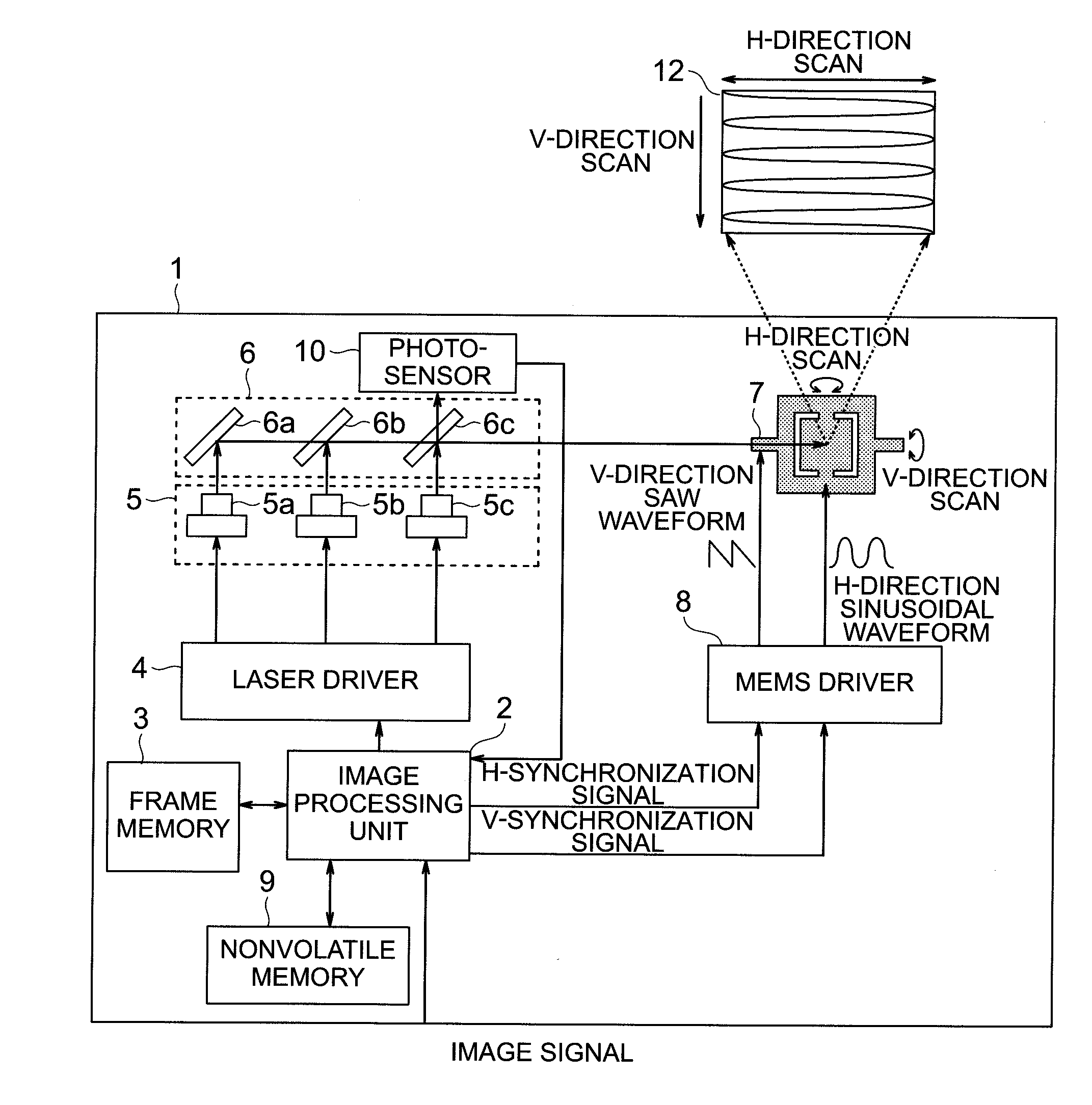
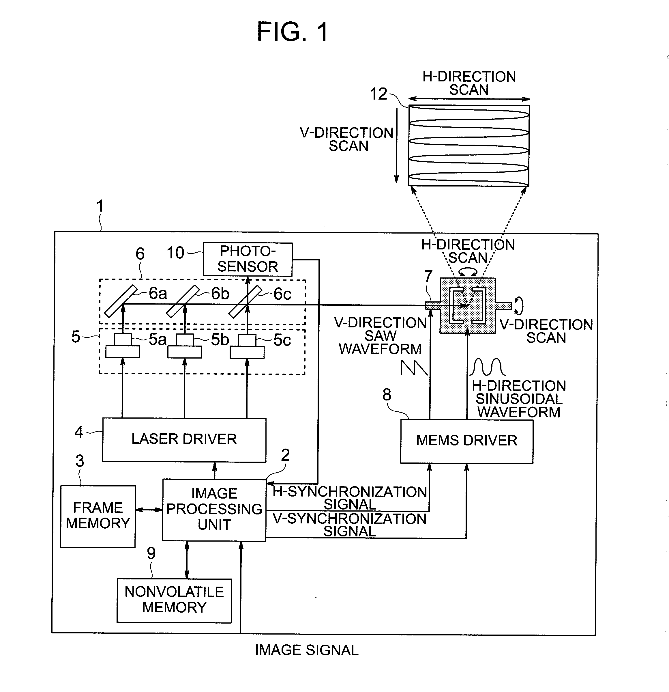
[0033]A configuration example of a projection type projector using MEMS in an embodiment of the present invention is shown in FIG. 1. A projection-type projector 1 comprises an image processing unit 2, a frame memory 3, a laser driver 4, a laser 5, a reflective mirror 6, a MEMS 7, a MEMS driver 8, a nonvolatile memory 9, a photosensor 10, a temperature sensor (not shown), and a display image 12. The temperature sensor may not be used in this embodiment. The image processing unit 2 generates an image signal, which is obtained by adding various corrections to an image signal input from the outside, and also generates a horizontal synchronizing signal and a vertical synchronizing signal in synchronization with this signal. Moreover, it also controls an image signal directed to the laser driver 4 in accordance with a light amount obtained from the photosensor 10 and adjusts the same so that the white balance becomes constant. The details thereof will be described later. Here, the variou...
embodiment 2
[0057]Next, Embodiment 2 in the present invention is described. FIG. 8 is a view showing an operation example of the embodiment. The difference from Embodiment 1 is the method of setting the reference value stored in the reference value unit 24, and other than this is the same as Embodiment 1, so the detailed description thereof is omitted.
[0058]In Embodiment 1, the reference values stored in the reference value unit 24 are two points R1 and R2. When there are only two reference value, input image data (D1, D2) equal to these reference values may not frequently appear, and the timing at which correction can be made may be limited. Then, in Embodiment 2, all the input image data that fall in between the reference values R1 and R2 shall be utilized. That is, all the write addresses A1 to An corresponding to the input image data D1 to Dn (n is an integer) that fall in between the reference values R1 and R2, as indicated by F1 of FIG. 8, are acquired. At the read addresses (A1 to An) of...
embodiment 3
[0060]Next, Embodiment 3 in the present invention is described. FIG. 9 is a view showing an operation example of the embodiment. A difference from Embodiment 1 and Embodiment 2 is a scheme, wherein assuming cases where image data will not fall in a range of the reference values stored in the reference value unit 24, a value is actively superimposed on the image data so that the image data thus superimposed falls in a range of the reference values of the reference value unit 24 (or the image data may be actively replaced by a value serving as a reference value). Because other than this scheme is the same as the Embodiment 1 and Embodiment 2, the detailed description thereof is omitted. In Embodiment 2, the range of the reference values in the reference value unit 24 is between R1 to R2. Input image data may not frequently fall in between these reference values R1 and R2, and thus the timing at which correction can be made may be limited. Then, in the Embodiment 3, if a reference valu...
PUM
 Abstract
Description
Claims
Application Information