
Resistive superconducting fault current limiter

a superconducting fault and limiter technology, applied in the direction of emergency protective arrangements for limiting excess voltage/current, basic electric elements, electrical equipment, etc., can solve the problems of limited fault current, serious problems, and large current loss so as to enhance the tolerance of superconducting limiter elements, reduce the size of the entire, and enhance the effect of toleran

Active Publication Date: 2009-07-07
LS IND SYETEMS CO LTD
View PDF10 Cites 41 Cited by
  • Summary
  • Abstract
  • Description
  • Claims
  • Application Information

AI Technical Summary

Benefits of technology

"The present invention provides a resistive superconducting fault current limiter that can reduce current loss and uniformly quench in the event of a fault current occurrence, thereby enhancing tolerance against high voltage. The invention also aims to reduce the size and fabrication cost of the superconducting limiter element. The technical effects of the invention include reducing current loss, minimizing magnetic field cancellation, and preventing overheating of the superconducting limiter element."

Problems solved by technology

Therefore, the fault current is limited.
However, even when a normal current less than a rated current flows the resistive type superconducting fault current limiter, the foil coil 16 applies a magnetic field to the superconducting limiter element 12 and the superconducting limiter element 12 generates a self magnetic field, which causes the superconducting limiter element 12 to have a great current loss.
The problems become serious when a rated voltage of the electric power system is higher.
As the result, the superconducting fault current limiter has an increased size thus to have a difficulty in obtaining an installation space thereof, and a fabrication cost thereof is increased

Method used


Image

  • Resistive superconducting fault current limiter
  • Resistive superconducting fault current limiter
  • Resistive superconducting fault current limiter

Examples


first embodiment

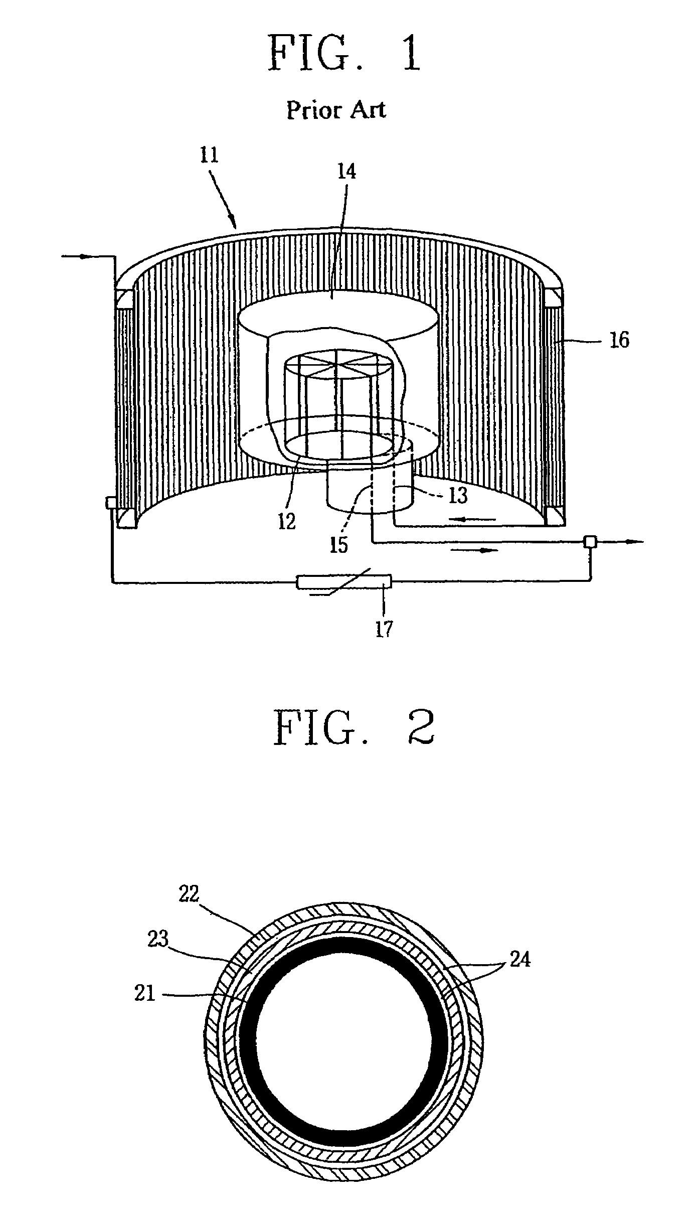
[0036]FIG. 2 is a sectional view showing a horizontal structure of a resistive superconducting fault current limiter according to the present invention.

[0037]As shown, the resistive superconducting fault current limiter according to a first embodiment of the present invention comprises: a superconducting limiter element 21 arranged at the innermost side thereof; a superconducting serial coil 22 arranged at the outermost side thereof so as to surround the superconducting limiter element 21; and a normal conductor parallel coil 23 arranged between the superconducting limiter element 21 and the superconducting serial coil 22.

[0038]The normal conductor parallel coil 23 is a solenoid shaped coil, and can be positioned between the superconducting limiter element 21 and the superconducting serial coil 22 as shown in FIG. 2. As another embodiment, the normal conductor parallel coil 23 can be also positioned outside the superconducting serial coil 22.

[0039]The resistive superconducting fault...

second embodiment

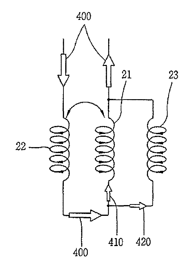
[0071]As shown in FIG. 6A, the resistive superconducting fault current limiter according to the present invention comprises a superconducting limiter element 21 which is in a superconductive state in the event of a normal current flow and changed into a normal conductive state having a predetermined resistance when a fault current having a predetermined threshold current value flows; a superconducting serial coil 22 serially connected to the superconducting limiter element 21; a first normal conductor parallel coil 23a connected to the superconducting limiter element 21 in parallel; and a second normal conductor parallel coil 23b connected to the superconducting serial coil 22 in parallel.

[0072]The superconducting limiter element 21 is a superconductor having a helical coil shape.

[0073]The superconducting serial coil 22 is serially connected to the superconducting limiter element 21 so as to face each other so that a current loss can be minimized accordingly as currents through them...


PUM


Abstract

A resistive superconducting fault current limiter comprises: a superconducting limiter element which is in a superconductive state in the event of a normal current occurrence, and which is in a normal conductive state having a predetermined resistance when a fault current larger than a predetermined threshold current value flows; a superconducting serial coil serially connected to the superconducting limiter element so as to face each other so that a current loss can be minimized accordingly as currents flow in opposite directions thus to cancel magnetic fields, and having a threshold current value greater than the threshold current value of the superconducting limiter element by a predetermined ratio; and a normal conductor parallel coil connected to the superconducting limiter element in parallel and having a predetermined resistance smaller than the resistance of the superconducting limiter element when a fault current occurs, for preventing the superconducting limiter element from being overheated by dividing a current flowing through the superconducting limiter element and for uniformly quenching the superconducting limiter element by generating a magnetic field when a fault current occurs

Description

BACKGROUND OF THE INVENTION[0001]1. Field of the Invention[0002]The present invention relates to a resistive superconducting fault current limiter, and more particularly, to a resistive superconducting fault current limiter capable of reducing a current loss of a superconducting limiter element due to a self magnetic field and an external magnetic field when a normal current is applied thereto, and capable of uniformly quenching the superconducting limiter element when a fault current such as a short circuit is applied thereto.[0003]2. Description of the Background Art[0004]A fault current limiter in an electric power system serves to limit mechanical, thermal, and electrical stresses applied to a bus bar, an insulator, a breaker, etc. of the electric power system when a fault current such as a short circuit, a ground fault, and a lightning strike occurs.[0005]A superconducting fault current limiter utilizes a principle that a superconductor is quenched by a fault current exceeding ...

Claims


Application Information

Patent Timeline
Patent Type & Authority Patents(United States)
IPC IPC(8): H02H9/00
CPCH02H9/023Y02E40/69Y10S505/85Y02E40/60H01H87/00
Inventor LEE, BANG-WOOKPARK, KWON-BAE
Owner LS IND SYETEMS CO LTD
Learn More