Ion current detection device for internal combustion engine

a technology of current detection and internal combustion engine, which is applied in the direction of machines/engines, mechanical equipment, instruments, etc., can solve the problems of inability to detect the knocking signal, preclude accurate measurement of the knocking signal, damage to the engine,

Inactive Publication Date: 2000-01-04
MITSUBISHI ELECTRIC CORP
View PDF9 Cites 43 Cited by
  • Summary
  • Abstract
  • Description
  • Claims
  • Application Information

AI Technical Summary

Problems solved by technology

Too early an ignition, however, causes an abnormal combustion, referred to as knocking, which may result in damage to the engine.
The optimum position of the oscillation sensor for detecting the oscillation of all cylinders without interference from other oscillation, such as from the intake and exhaust valves, varies from one type of engine to another and is an important issue in engine design.
Thus the ringing creates signals similar to the oscillating component of the ion current at the output of the band-pass filter, and hence precludes an accurate measurement of the knocking signal.
This means that the detection of the knocking cannot be made until the oscillating signal due to the ringing becomes sufficiently small compared with the oscillating signal due to the knocking.
The knocking cannot be detected during this period of time.
It is well known, however, that the band-pass filter, which is designed to minimize the duration of the ringing, cannot detect knocking.
The masking circuit 207 removes the high frequency component from the voltage signal obtained by the ion current / voltage conversion circuit 204 which cannot be removed by the operational amplifiers because of its poor circuit responsiveness.
Therefore, processing of the ion current with the band-pass filter without preprocessing it gives rise to a ringing immediately after the ion current is generated, thereby resulting in a false detection of the knocking current causing the system to falsely determine that a knocking has occurred even if it has not.
Further, the ion current detection device shown in FIG. 18 requires many operational amplifiers.
Therefore, it is large and expensive.

Method used


Image

  • Ion current detection device for internal combustion engine
  • Ion current detection device for internal combustion engine
  • Ion current detection device for internal combustion engine

Examples


embodiment 1

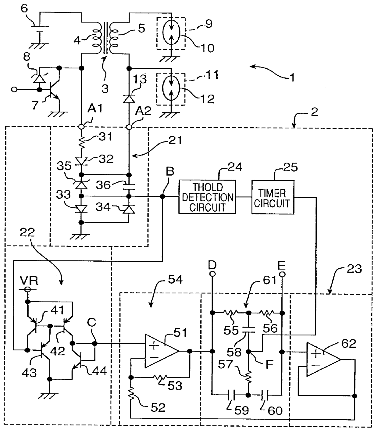
FIG. 1 illustrates a circuit diagram of the ion current detection device of Embodiment 1 of the present invention. Referring to FIG. 1 an ignition device 1 of the simultaneous firing type is connected to an ion current detection device 2 at the terminals A1 and A2. The ignition device 1 includes an ignition coil 3 having a primary coil 4 and a secondary coil 5. One end of the primary coil 4 is connected to the positive electrode of a battery 6 with the negative electrode of the battery 6 being grounded.

The other end of the primary coil 4 is connected to the collector of an npn transistor 7 for controlling the primary current of the ignition coil 3. The cathode of a Zener diode 8 limits the collector voltage of the npn transistor 7 or that of the terminal A1. The emitter of the npn transistor 7 is grounded. The base of the npn transistor 7 is connected to the anode of the Zener diode 8 and receives an ignition control signal provide by an ignition control computer unit (not shown). T...

embodiment 2

Embodiment 1 includes a buffer circuit using a voltage follower formed with the operational amplifier 62 as a means for impedance conversion for the voltage at the output terminal E of the band-pass filter 23. The buffer circuit, however, can be formed with a transistor circuit for the same purpose. The embodiment of the ion current detection device including a buffer circuit formed with a transistor circuit is referred to as Embodiment 2.

FIG. 14 illustrates a circuit diagram of part of the ion current detection device of Embodiment 2 of the present invention. The like reference numerals of FIGS. 14 and 1 indicate identical or functionally similar elements. Thus explanation of those elements will not be repeated. FIG. 14 only shows the portion of the circuit which is different from FIG. 1 and only the differences with FIG. 1 will be described below.

The difference between FIG. 14 and FIG. 1 is that the operational amplifier 62 of the band-pass filter 23 in FIG. 1 is replaced by an im...

embodiment 3

The impedance conversion circuit 101 of Embodiment 2 may be formed with an npn transistor at its input and a pnp transistor at its output. Embodiment 3 is the ion current detection device with this modified impedance conversion circuit.

FIG. 15 illustrates a circuit diagram of part of the ion current detection device of Embodiment 3 of the present invention. The like reference numerals of FIGS. 15 and 14 indicate identical or functionally similar elements. Thus explanation of those elements will not be repeated and only the difference between FIG. 15 and FIG. 14 will be described below.

The difference between FIG. 15 and FIG. 14 is that the impedance conversion circuit 101 in FIG. 14 is replaced with an impedance conversion circuit 111. In reflecting this change the band-pass filter of Embodiment 3, corresponding to the band-pass filter 102 in FIG. 14, is referred to as the band-pass filter 112, and the ion current detection device of Embodiment 3, corresponding to the ion current det...


PUM


Abstract

An ion current detection device of an internal combustion engine includes a detection voltage generation device which applies a voltage to an ignition plug to generate an ion current in a cylinder of the engine. A current to voltage conversion circuit detects and converts the generated ion current to a voltage signal. A bandpass filter extracts an ac component within a specified frequency range from the voltage signal produced by the current to voltage conversion circuit. An ion current threshold detection portion produces an ion current detection signal when the detected ion current exceeds a predetermined threshold current. A filter characteristic control circuit controls the characteristic of the bandpass filter to suppress the sensitivity of the filter for a predetermined period of time right after the ion current detection signal is detected and, after the predetermined period of time, increase the sensitivity of the filter for detection of the ac signal with the specific frequency.

Description

1. Field of the InventionThe present invention relates to an ion current detection device which detects the ion current caused by ionized combustion gas within an internal combustion engine in order to detect combustion states in cylinders of the engine.2. Description of the Prior ArtAn ignition type internal combustion engine (referred to as an engine hereinafter) produces power by compressing a fuel gas mixed with air in a combustion chamber (referred to as a cylinder hereinafter) with a piston and then igniting the mixed gas with an ignition plug. The power derived from the engine depends on the ignition timing with regard to the position of the piston. Generally an earlier ignition produces higher power. Too early an ignition, however, causes an abnormal combustion, referred to as knocking, which may result in damage to the engine. In order to avoid knocking, a conventional engine is provided with an oscillation sensor for detecting oscillation of the engine and determines an oc...

Claims


Application Information

Patent Timeline
Patent Type & Authority Patents(United States)
IPC IPC(8): F02P17/12G01M15/04
CPCF02P17/12
Inventor YASUDA, YUKIO
Owner MITSUBISHI ELECTRIC CORP
Why Eureka
Try Eureka