Optical Signal Processing

a technology of optical signal and optical frequency, applied in the field of optical signal processing, can solve the problems of wasting valuable transmission bandwidth, requiring impractically low residual dispersion post-compensation, and power consumption as well as significant computing overhead associated with the aforementioned electronic functions. achieve the effect of reducing phase nois

Active Publication Date: 2013-08-15
UNIV OF SOUTHAMPTON
View PDF1 Cites 26 Cited by
  • Summary
  • Abstract
  • Description
  • Claims
  • Application Information

AI Technical Summary

Benefits of technology

[0010]A pre-processing stage may be added to receive an optical amplitude modulated signal and convert it to an optical phase modulated signal, optionally in combination with a post-processing stage arranged to receive the regenerated optical phase modulated signal and reconvert it to an amplitude modulated signal. This allows multi-level amplitude modulated signals to be regenerated.
[0011]An embodiment of the pre-processing stage may include a multi-level amplitude modulated signal, and a modulation free pump source, a first section of non-linear optical material arranged to receive the signal and the pump, in which the pump and the signal are subject to cross phase modulation to transfer the amplitude modulation on the signal to phase modulation on the pump. The phase modulated pump is then used as the input signal to an optical phase regenerator; and at the regenerator output the regenerated phase modulation is converted back to amplitude modulation e.g. by

Problems solved by technology

However, the power consumption as well as the significant computing overhead associated with the aforementioned electronic functions means (see, for example, K. Roberts et. al., J. Lightwave Technol.
One proposed scheme utilises a pair of conjugated signal-idler channels transmitted along the link and combined in a non-degenerate PSA (see, for example, M. Vasilyev, Opt. Exp., 13, 7563; 2005); however this wastes val

Method used


Image

  • Optical Signal Processing
  • Optical Signal Processing
  • Optical Signal Processing

Examples


Embodiment Construction

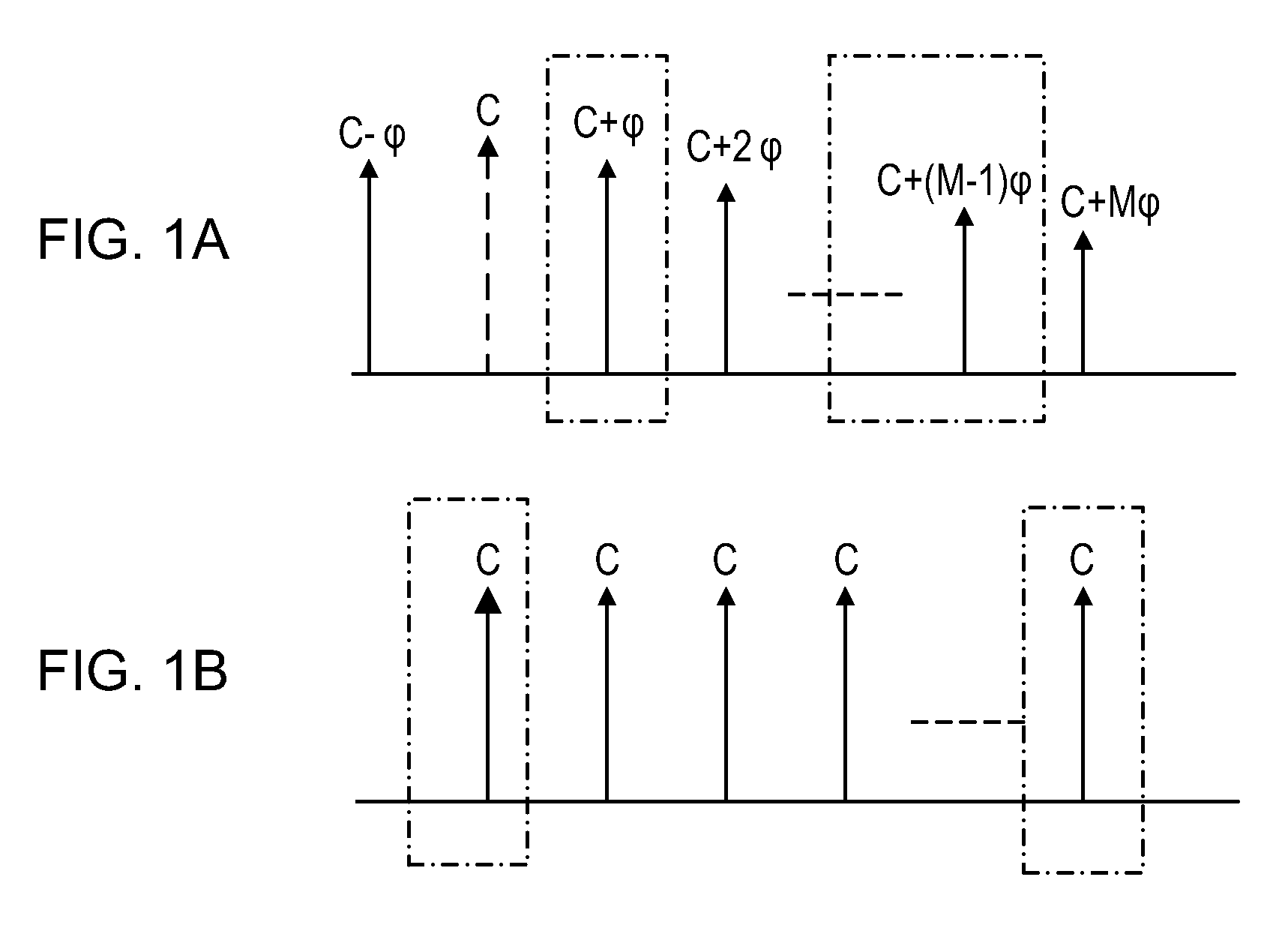
[0040]FIGS. 1(a) and (b) show a conceptual diagram showing frequency components relevant for an optical regenerator according to a first embodiment for regenerating a multi-level phase encoded signal, where multi-level means more than binary, such as the four levels used in quadrature keying.

[0041]FIG. 1(a)—the upper part of the figure—shows a sequence of signal components generated by four wave mixing (FWM) of a phase encoded signal of the wavelength of the (zeroth order) component labeled C with a pump signal having a wavelength offset from the signal frequency. The signal components are separated equally in frequency or energy. It is also a good approximation to consider the signals to be equally separated in wavelength, and generally the plots in this document show wavelength rather than frequency or energy following convention. Generally a signal with phase encoded data of phase φ can be converted by four wave mixing with a pump signal having a wavelength offset from the signal...


PUM


Abstract

An optical regenerator for regenerating a multi-level phase encoded signal. A first non-linear medium (HNLF1) generates a comb of frequency harmonics from the signal under the action of a coherent pump, each component bearing the phase encoded data. A filter selects the first and (M−1)th order components. The filtered signal is then input to a second non-linear medium (HNLF2) where a further pump is applied, to coherently add the first and (M−1)th order components and regenerate the signal by reducing phase noise.

Description

BACKGROUND OF THE INVENTION[0001]The invention relates to optical signal processing, and in particular an optical device for regenerating optical signals containing phase-encoded data, or quantizing the phase of any input phase modulated signal.[0002]The future of optical fiber communications will be dictated by the need for long reach, high capacity and energy efficient technologies. Transitioning to spectrally efficient modulation formats such as quadrature phase shift keying (QPSK) provides significant capacity gains in long haul optical links. Fully coherent optical signal detection combined with high speed analog-to-digital conversion allows signal processing in the electronic domain, providing capabilities such as compensation for chromatic and polarization mode dispersion, as well as for some of the accumulated nonlinear phase noise which is the dominant limitation in extending coherent transmission spans (see, for example, E. Ip et. al., Opt. Express 16, 753-791; 2008).[0003...

Claims


Application Information

Patent Timeline
IPC IPC(8): G02F1/01H04B10/291
CPCH04B10/291H01S3/0092G02F1/01
Inventor KAKANDE, JOSEPHPARMIGIANI, FRANCESCAPETROPOULOS, PERIKLISRICHARDSON, DAVID JOHNSLAVIK, RADEN
Owner UNIV OF SOUTHAMPTON
Why Eureka
Try Eureka