Method for operating a brake system, brake systems in which the method is carried out and motor vehicles comprising said brake systems

Active Publication Date: 2013-08-15
CONTINENTAL TEVES AG & CO OHG
View PDF1 Cites 11 Cited by
  • Summary
  • Abstract
  • Description
  • Claims
  • Application Information

AI Technical Summary

Benefits of technology

The invention relates to a brake system for vehicles that allows for efficient energy regeneration and optimal driver comfort during braking. The system uses a generator to produce braking torque, which is combined with the traditional hydraulic braking system. The brake fluid is displaced during the operation of the brake pedal, even for a purely regenerative braking situation. This allows for a constant relationship between pedal displacement and vehicle deceleration, ensuring maximum use of the generator braking torque. The braking effect of the generator can be fully utilized, but the brake fluid may not be conducted directly into the brakes. Instead, the brake fluid is conducted into a reservoir, and the volume of brake fluid introduced into the reservoir is dimensioned in a suitable manner. The start and end of the introduction of the brake fluid into the reservoir can be performed by opening or closing at least one outlet valve. The driver experiences the same or essentially the same relationship between pedal displacement and braking torque or vehicle deceleration as for normal hydraulic braking, so they do not have to get used to different behavior of the brake pedal with regard to the associated braking torque. The invention provides a motor vehicle with optimized comfort during braking and efficient energy regeneration.

Problems solved by technology

If such a decoupling does not occur, i.e., if braking also takes place with the operating brakes in parallel with the generator, the available generator braking torque cannot be used in the maximum possible way.

Method used


Image

  • Method for operating a brake system, brake systems in which the method is carried out and motor vehicles comprising said brake systems
  • Method for operating a brake system, brake systems in which the method is carried out and motor vehicles comprising said brake systems
  • Method for operating a brake system, brake systems in which the method is carried out and motor vehicles comprising said brake systems

Examples


Embodiment Construction

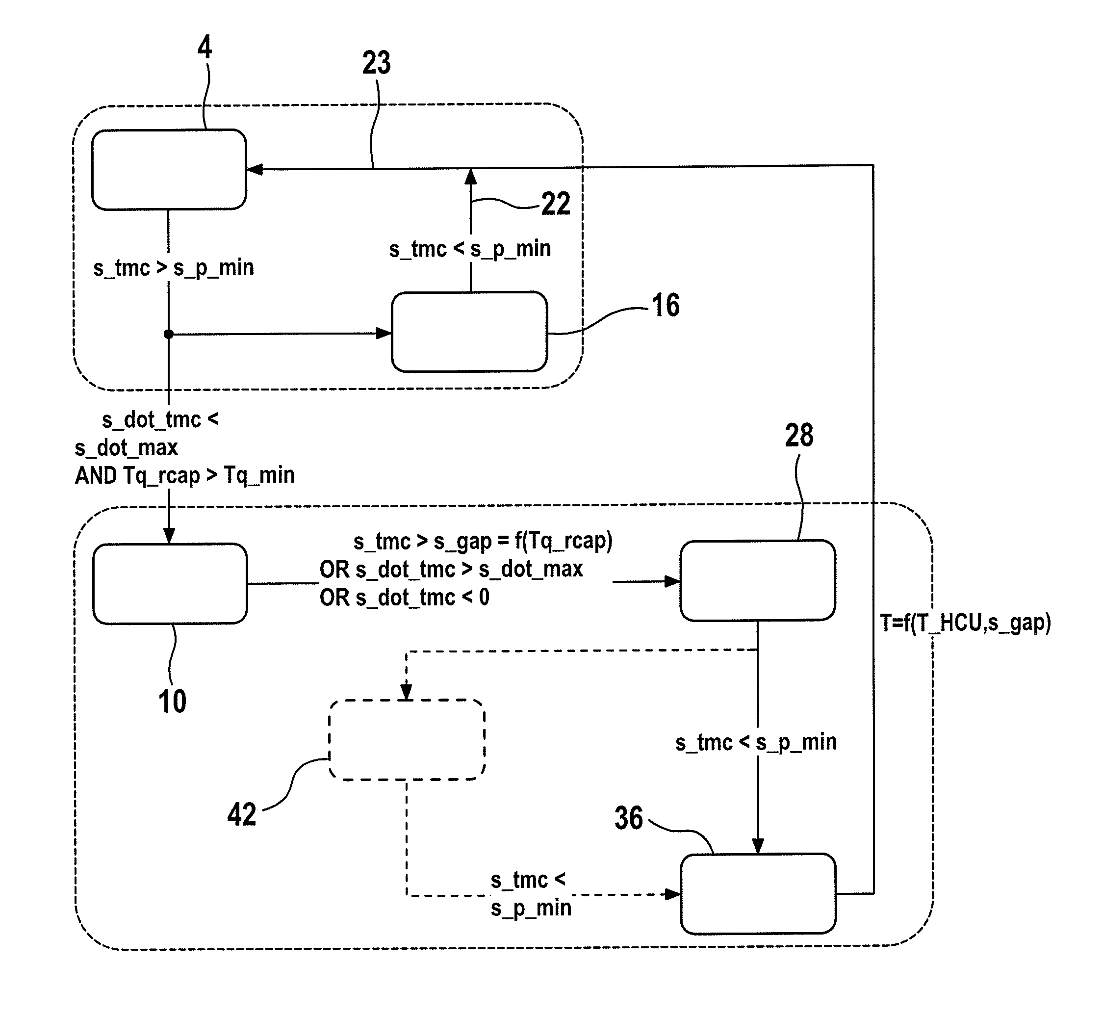
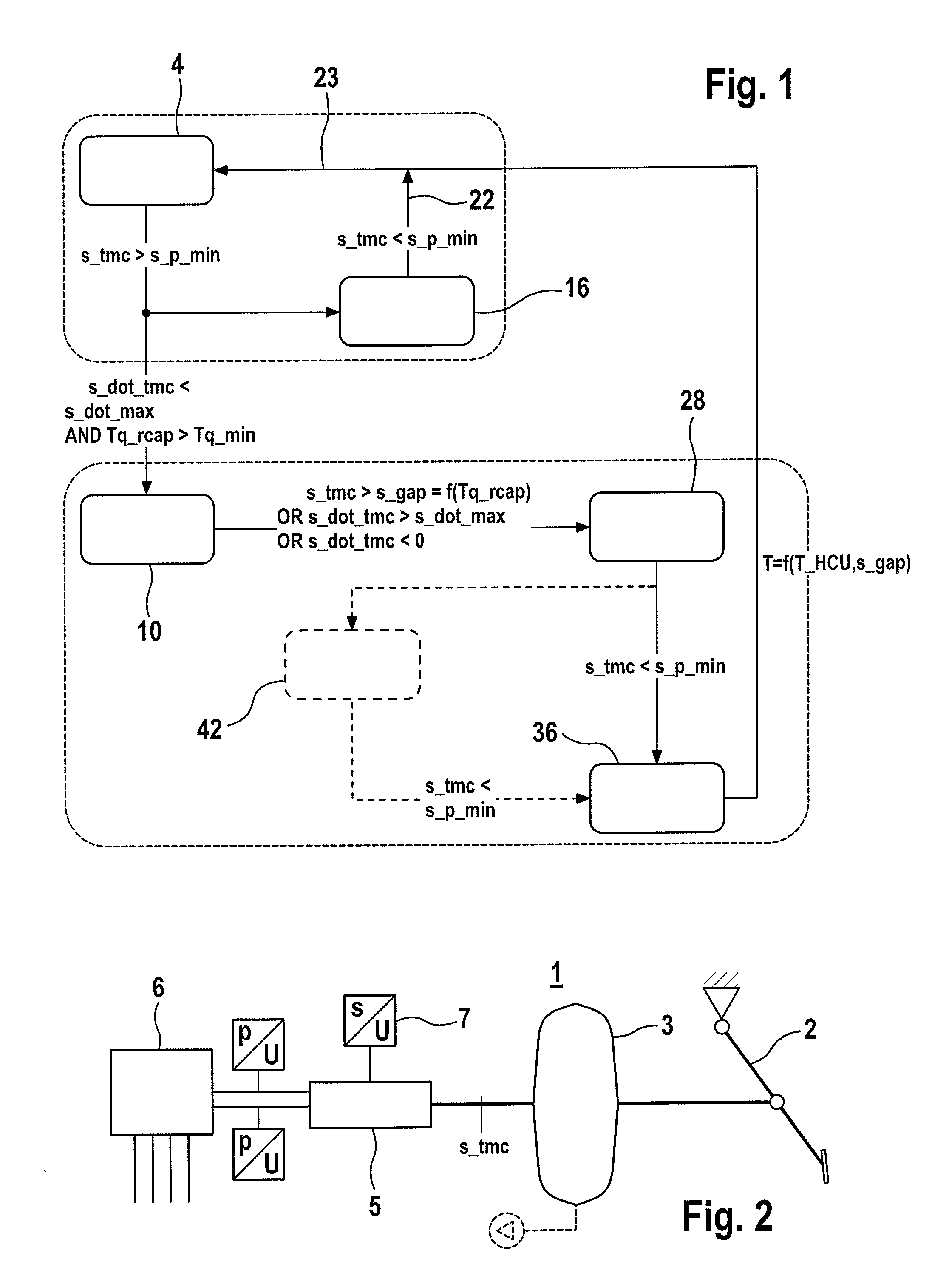
[0045]A method for the operation of a brake system in a first preferred embodiment for an electrohydraulic brake system is explained below using the state diagram shown in FIG. 1. An associated implementation of a conventional hydraulic brake system 1 according to the prior art with a brake pedal 2, a booster 3, a master brake cylinder 5 and a recuperative brake system 6 is illustrated in FIG. 2. The recuperative brake system 6 advantageously comprises hydraulic and electronic components for implementing an ESC (Electronic Stability Control) program. A displacement sensor 7 is provided for determination of the travel of the master cylinder 5.

[0046]The functionality or the process step of hydraulically implementing the free travel of the brake pedal necessary for regenerative braking by displacement of a volume of brake fluid into a reservoir is referred to below as an electrohydraulic gap or eGap. Said term is equally used for the braking volume displaced in this manner.

[0047]Starti...


PUM


Abstract

A method for the operation of a brake system having two brake circuits, with a recuperative brake, in particular an electrical generator, a master brake cylinder and a brake pedal simultaneously achieve optimized use of the regenerative braking and a constant braking experience for the driver with the highest safety requirements. When there is a braking demand by the driver with an associated desired braking torque and a first condition is met, at least one outlet valve is opened and brake fluid is conducted with an associated volume of brake fluid into at least one reservoir and the at least one outlet valve is then closed if a second condition is met. The first condition is met if a braking variable corresponding to the braking demand is not less than a specified minimum value. The second condition is met if the volume of brake fluid has flowed into the reservoirs.

Description

CROSS REFERENCE TO RELATED APPLICATIONS[0001]This application is the U.S. National Phase of PCT International Application No. PCT / EP2011 / 065157, filed Sep. 1, 2011, which claims priority to German Patent Application No. DE 10 2010 040 190.0, filed Sep. 3, 2010, the contents of such applications being incorporated by reference herein.FIELD OF THE INVENTION[0002]The invention relates to a method for the operation of a brake system having two brake circuits, having a regenerative brake, in particular an electrical generator, a master brake cylinder and a brake pedal. It further relates to associated brake systems and a motor vehicle.BACKGROUND OF THE INVENTION[0003]The electric motor is gaining increasing importance as a replacement for or as a complement to internal combustion engines for driving motor vehicles. This is happening inter alia because of the environmental compatibility and the energy efficiency. The electric motor has still further advantages compared to the internal com...

Claims


Application Information

Patent Timeline
IPC IPC(8): B60T13/58
CPCB60T1/10B60T8/267B60T8/3275B60T8/4077B60T8/4081B60T8/4872B60T13/586B60T2270/402B60T2270/604B60W10/08B60W10/188B60W30/18127B60W2540/12B60T13/686B60T8/26B60T8/48
Inventor ULLRICH, THORSTENALBRICH VON ALBRICHSFELD, CHRISTIANKARNER, JURGENFUHRER, JOCHEN
Owner CONTINENTAL TEVES AG & CO OHG
Why Eureka
Try Eureka