Fuel pump with quiet cam operated suction valve

Inactive Publication Date: 2013-08-22
FORD GLOBAL TECH LLC
View PDF29 Cites 9 Cited by
  • Summary
  • Abstract
  • Description
  • Claims
  • Application Information

AI Technical Summary

Benefits of technology

[0004]By operating the metering valve via a cam, it may be possible to reduce the impact velocity between a metering valve and housing. As a result, a cam that operates the metering valve can be rotated with very little noise. Additionally, the cam operated metering valve can open without producing a striking noise. Consequently, both metering valve opening and closing noises

Problems solved by technology

The impact can produce a ticking

Method used


Image

  • Fuel pump with quiet cam operated suction valve
  • Fuel pump with quiet cam operated suction valve
  • Fuel pump with quiet cam operated suction valve

Examples


Example

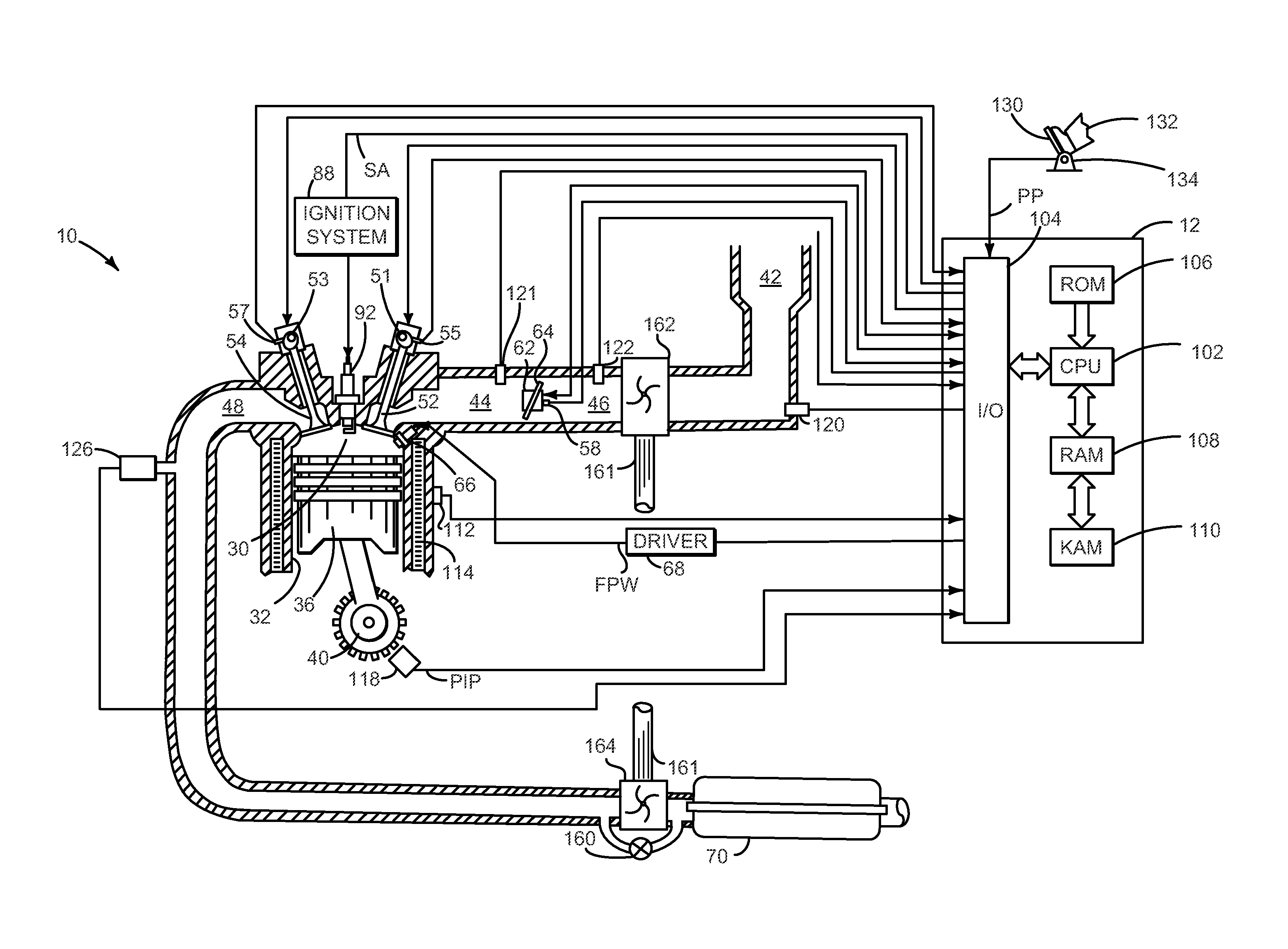
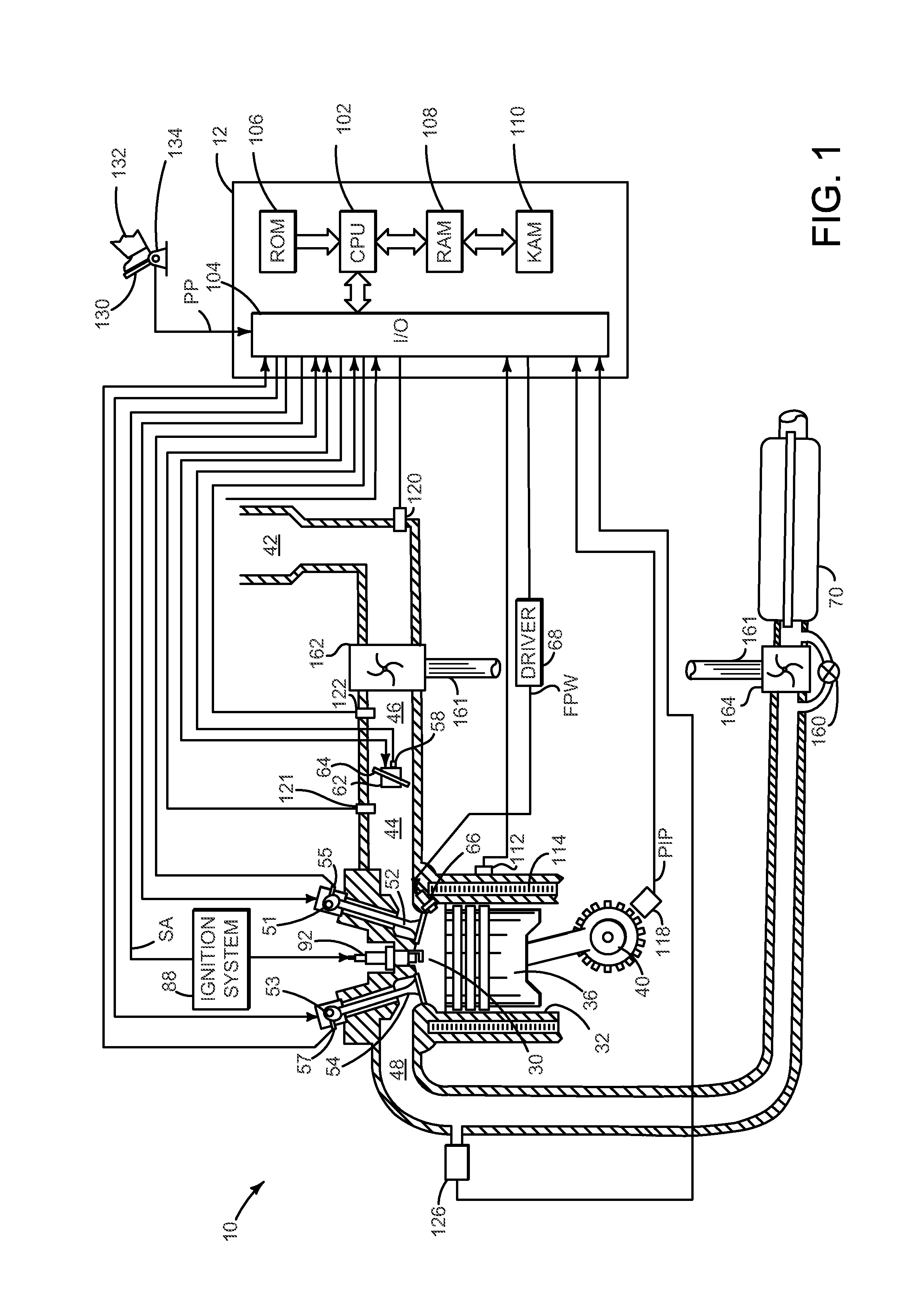
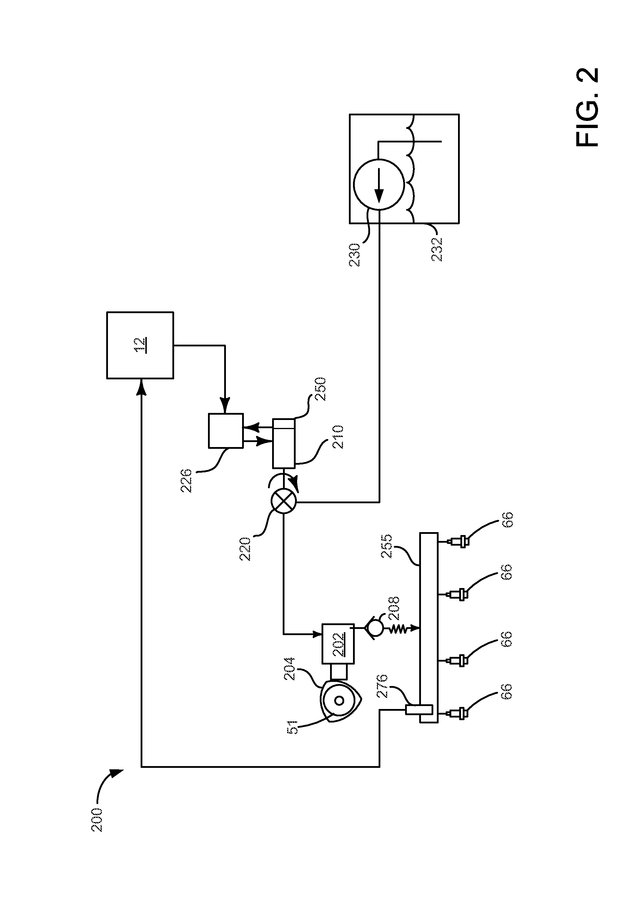
[0018]The present description is related to a fuel system for directly injecting fuel into cylinders of an engine. FIG. 1 shows an example direct injection gasoline engine. However, the fuel system described herein is equally applicable to diesel engines. FIG. 2 shows schematic of an example fuel system including a fuel pump and metering valve.

[0019]FIGS. 3A-3C show one example fuel pump and metering valve. FIGS. 4A-4B show example sequences for operating the fuel pump and metering valve shown in FIGS. 3A-3C. An alternative fuel pump and metering valve are shown in FIGS. 5A-5B. FIGS. 6A-6B show example sequences for operating the fuel pump and metering valve shown in FIGS. 5A-5B. Another alternative fuel pump and metering valve are shown in FIGS. 7A-7D. FIGS. 8A-8B show example sequences for operating the fuel pump and metering valve shown in FIGS. 7A-7D. The fuel pumps and metering valves described in FIGS. 2-8 may be operated according to the method of FIG. 9.

[0020]Referring to FI...


PUM


Abstract

A fuel system including a high pressure fuel pump with a quite fuel metering valve is disclosed. In one example, the quite fuel metering valve may be cam driven. The fuel system may reduce engine noise and may provide operating modes that are different from other fuel systems.

Description

FIELD[0001]The present description relates to a high pressure fuel pump for supplying fuel to an internal combustion engine. The high pressure fuel pump may be particularly useful for engines that include fuel injectors that inject fuel directly into engine cylinders.BACKGROUND AND SUMMARY[0002]Diesel and direct injection gasoline engines have fuel injection systems that directly inject fuel into engine cylinders. The fuel is injected to an engine cylinder at a higher pressure so that fuel can enter the cylinder during the compression stroke when cylinder pressure is higher. The fuel is elevated to the higher pressure by a mechanically driven fuel pump. Fuel pressure at the outlet of the fuel pump is controlled by adjusting an amount of fuel that flows through the fuel pump. One way to control flow through the fuel pump is via a solenoid operated metering valve. In one example, the solenoid is operated to close the metering valve during a pumping phase of the fuel pump. Closing the ...

Claims


Application Information

Patent Timeline
IPC IPC(8): F02M59/20F02M59/00
CPCF02M2200/09F02M59/361F02M63/0265F02M63/0038
Inventor ZENG, PAULSOLFERINO, VINCE PAULSHIAH, KYIBASMAJI, JOSEPHBROSTROM, PATRICK
Owner FORD GLOBAL TECH LLC
Why Eureka
Try Eureka