Common to the aforementioned is that the action of the knives against the wood subjects the knives to considerable
cutting forces.
Since the repeated action of the knives against the wood also results in wear, the machines must also be designed so as to allow for the periodic replacement of the knives.
This can involve cumbersome working situations where workers need to reach around components of the
machine to effectuate a knife change, or limitations in time available between production periods to attend to all aspects of the work in a detailed and thorough fashion.
Such minor damage can easily go unnoticed in a production environment.
Such bodies, with their varied forms, impose various geometrical and functional constraints.
The requirements of many modern day machines impose additional demands on the knife clamping
assembly.
The need to operate at evermore increasing production speeds for
cost competitiveness has resulted in
machine designs with increasingly higher knife counts, and accordingly, limited amounts of space available for the knives and knife clamping assembly on the base member.
However as a result of the rather
large size of the knife elements themselves, the clamping assemblies are typically bulky devices consuming significant space on the base member.
Their compact nature precludes them from being primary
load bearing elements and renders them significantly more difficult to secure within the clamping assembly.
Blades of the reversible type also
pose additional constraints on the clamping assembly in that the clamping components cannot contact the knife in areas adjacent the unexposed
cutting edge(s) since these edges can often be damaged from prior use.
Already limited due to their smaller size, this further diminishes the support and contact areas that can be employed to maintain the knives in a stable position during operation.
When properly sized and constructed, clamping assemblies based on this principle can also generate high clamping forces for securing the knives under the action of the
cutting forces.
However they are not without problems.
While simple and mechanically reliable, the force developed by the
fastener is often difficult to predict and control with accuracy.
Such factors as the variation in the
fastener's tightening force (torque) and unpredictable nature of friction between contact surfaces result in a wide range of force developed by the
fastener.
Further, because of the need for knife assemblies to be of a
compact form to integrate properly with the foundation bodies, it is not always possible to achieve a third order configuration that is favourable for the development of high clamping pressures.
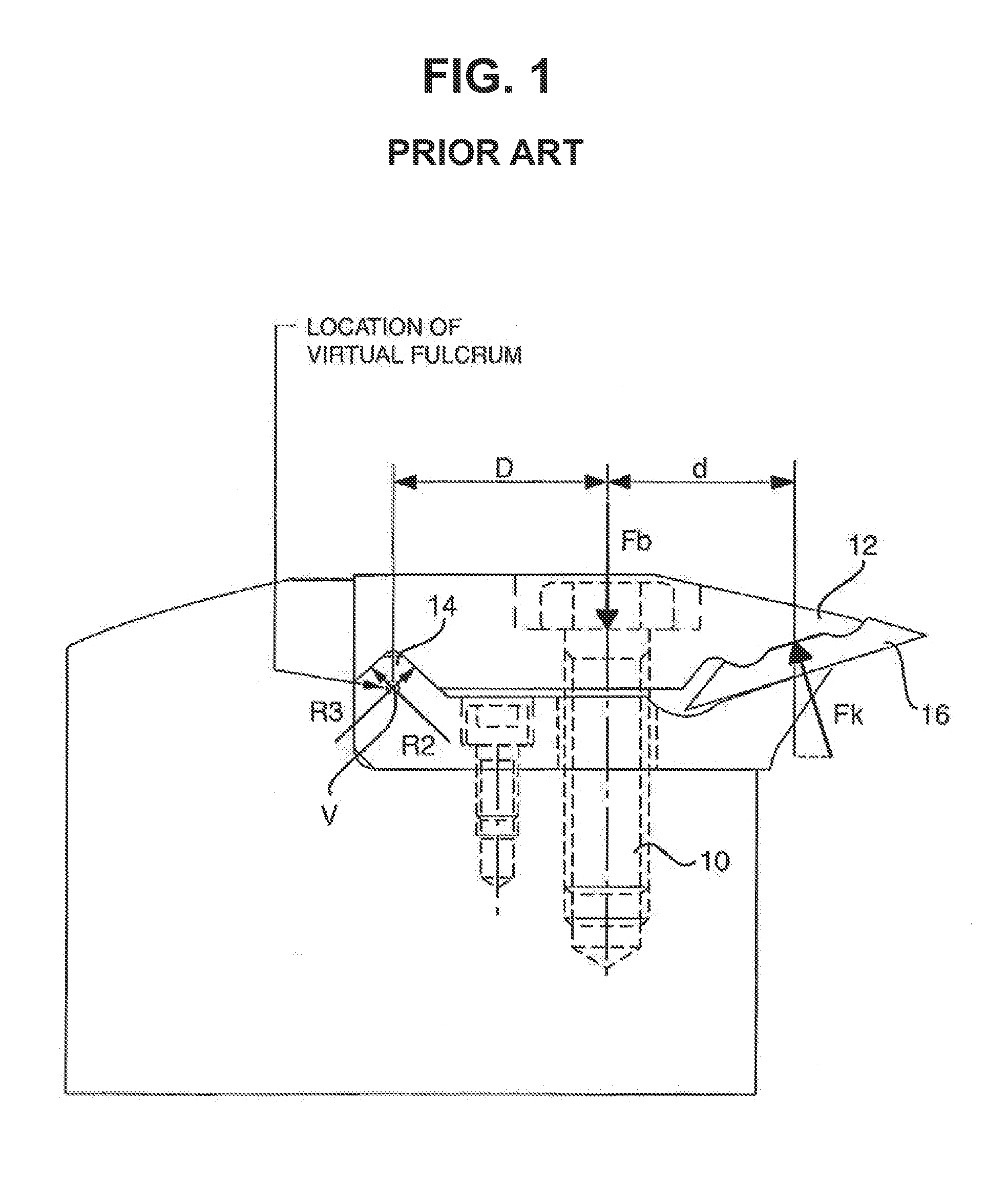
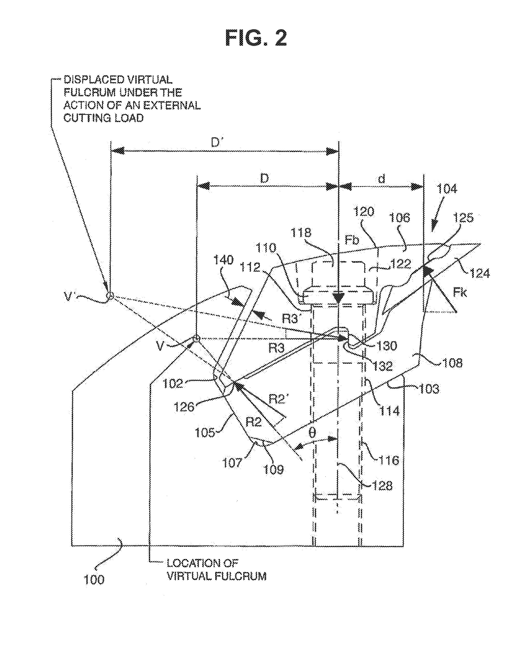
With many base members, space constraints limit the placement of the fulcrum.
This means that the size of the clamping force, and thereby the ability to carry external cutting loads, is dictated by the capabilities of the
actuator, which is often variable and difficult to control as noted above.
In general, the requirement for compactness and high knife clamping pressures conspire to limit the strength that can be obtained with a third order assembly.
While the fastener must be of sufficient size to provide the necessary force for securing the knife under the action of the cutting forces, it cannot be of a size or a form that would consume excessive amounts of space within the assembly.
This could result in clamping components that are inadequately sized and shaped for acceptable strength to be achieved.
While an oversized fastener may ensure that an adequate preload force is developed under all circumstances, it can result in unacceptable stresses within the individual components that comprise the clamping assembly.
Further, these smaller fasteners lack rigidity which results in a clamping assembly of lower stiffness such that the displacement of the knife edge under the action of the cutting forces can be problematic.
This often mandates that the fasteners be tightened to precise values using specialized equipment, and that the
lubrication, cleanliness, and general condition of the fasteners be scrutinized In the absence of such measures, inadequate bolt preload can compromise the function of the clamping assembly.
This can lead to the knives being improperly secured in service.
While the aforementioned alternatives offer advantages in the form of stronger more rigid clamping assemblies that are less susceptible to inadequate preload being developed by the actuator, they suffer from some notable disadvantages as well.
In general, such assemblies do not exhibit the same high ease of use as simple third order clamping assemblies constructed from two clamping components.
As a result of reduced
accessibility or added complexity, it can be more difficult for workers to make a knife change, in particular to clean the assembly of any wood debris.
Such material, if left in place, could compromise the function and reliability of the assembly.
Generally as a result of their size and shape, they do not integrate well with all forms of base members and cannot be easily retrofitted to existing machines.

