Metal fuse structure for improved programming capability

a fuse structure and programming capability technology, applied in the field of electric fuses, can solve the problems of increasing the difficulty of implementing fuses at the poly level, collateral damage, dielectric material to fracture, etc., and achieve the effect of more controllable and predictable final resistan

Inactive Publication Date: 2013-08-22
GLOBALFOUNDRIES INC
View PDF0 Cites 22 Cited by
  • Summary
  • Abstract
  • Description
  • Claims
  • Application Information

AI Technical Summary

Benefits of technology

[0008]The general principal of the present invention is to intentionally damage a portion of a fuse structure so that the fuse will blow at that damaged location. By damaging a por

Problems solved by technology

As scaling progresses, it is becoming harder to implement fuses at the poly level due to drop in maximum allowable currents through the first metal layer or conductor.
Also, the collateral damage (namely movement of fuse material causing neighboring dielectric material to fracture) associated with fuse blow is becoming more difficult to contain.
Furthermore, the horizontal structure of the fuse consumes valuable chip re

Method used


Image

  • Metal fuse structure for improved programming capability
  • Metal fuse structure for improved programming capability
  • Metal fuse structure for improved programming capability

Examples


Embodiment Construction

[0025]Various embodiments of the fuse structure of the present invention are described in conjunction with FIGS. 2-6. Embodiments of methods of making the fuse structures of the present invention are described in conjunction with FIGS. 7-8f.

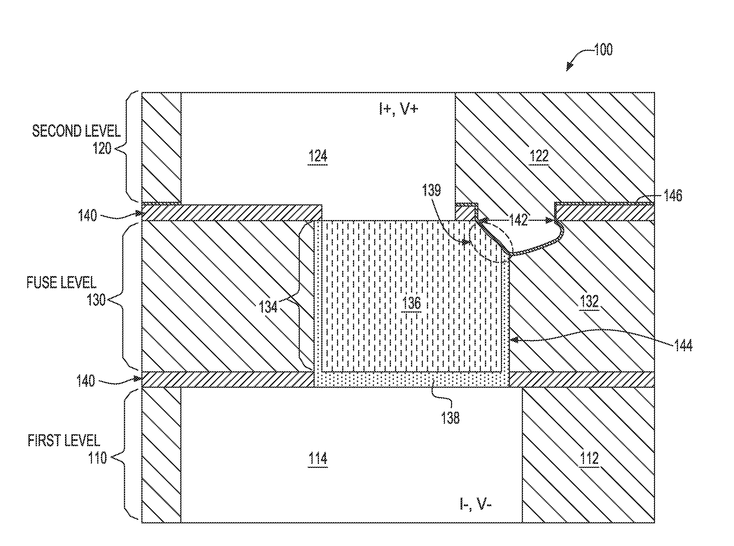
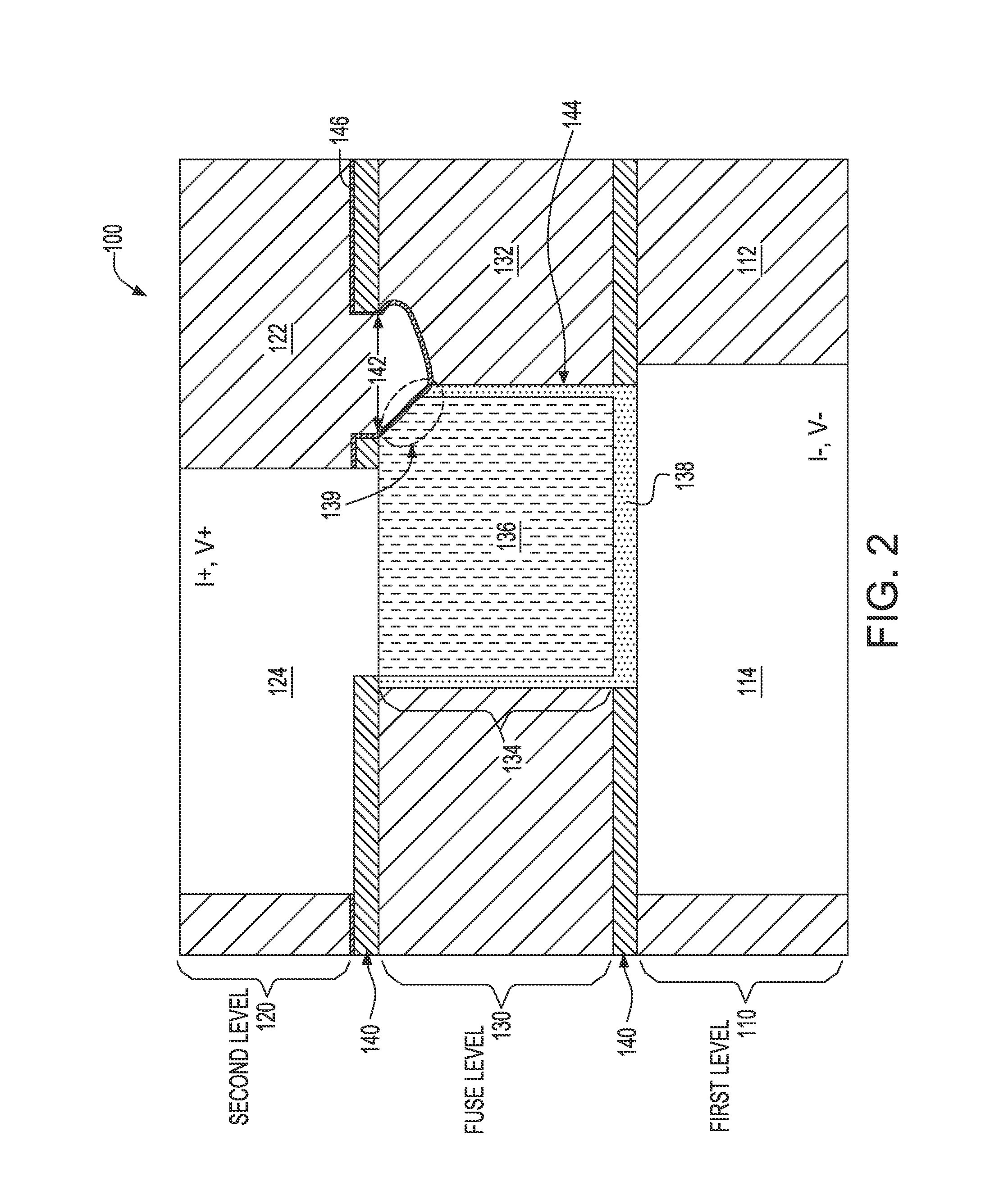
[0026]Referring to FIG. 2, a fuse structure 100 prior to fuse blow is illustrated. On a substrate (not shown) is a first level 110, a second level 120 and a fuse level 130. The fuse level 130 is between the first 110 and second 120 levels. Each level includes an insulator and a conductor. The levels are separated by a cap layer 140. The first, second and fuse level insulators are denoted by reference numerals 112, 122, and 132 respectively. The first, second and fuse level conductors are denoted by reference numerals 114, 124, and 134 respectively. Each of the conductors 114, 124 and 134 can include a bulk conductor and a liner. In FIG. 2, the bulk conductor 136 and liner 138 are only shown for the fuse conductor 134 for ease if viewing. It shou...


PUM

PropertyMeasurementUnit
Timeaaaaaaaaaa
Dielectric polarization enthalpyaaaaaaaaaa
Structureaaaaaaaaaa

Abstract

Structure providing more reliable fuse blow location, and method of making the same. A vertical metal fuse blow structure has, prior to fuse blow, an intentionally damaged portion of the fuse conductor. The damaged portion helps the fuse blow in a known location, thereby decreasing the resistance variability in post-blow circuits. At the same time, prior to fuse blow, the fuse structure is able to operate normally. The damaged portion of the fuse conductor is made by forming an opening in a cap layer above a portion of the fuse conductor, and etching the fuse conductor. Preferably, the opening is aligned such that the damaged portion is on the top corner of the fuse conductor. A cavity can be formed in the insulator adjacent to the damaged fuse conductor. The damaged fuse structure having a cavity can be easily incorporated in a process of making integrated circuits having air gaps.

Description

BACKGROUND OF THE INVENTION[0001]1. Field of the Invention[0002]The present invention generally relates to electrical fuses in microelectronic devices and a method of making metal fuses. In particular, the invention relates to damaging a metal structure to control the location of fuse blow.[0003]2. Description of Related Art[0004]In advanced technologies, e-fuses have been implemented at the gate level where a fuse structure includes a narrow, horizontal, polycrystalline silicon (herein “poly”) line topped by a silicide. During programming, a high current (i.e. high current density) is passed through the structure. High current density causes the silicide to irreversibly migrate from the top of the poly to throughout the line, causing a change in resistance and thus acting as a programmable fuse. In poly fuses, the fuse structure is often placed over oxide isolation areas. The dielectric properties of the isolation oxide keep in the heat generated by current flow, thus increasing th...

Claims


Application Information

Patent Timeline
IPC IPC(8): H01H85/04H01H69/02
CPCH01H69/02Y10T29/49107H01H2085/0275H01H85/046H01L2924/0002H01L2924/00H01L23/5226H01L23/5256H01L23/528
Inventor BONILLA, GRISELDACHANDA, KAUSHIKCHOI, SAMUEL S.FILIPPI, RONALD G.GRUNOW, STEPHANLUSTIG, NAFTALI E.SIMON, ANDREW H.
Owner GLOBALFOUNDRIES INC
Why Eureka
Try Eureka