Light-adjusting unit and projector

a technology of light-adjusting unit and projector, which is applied in the direction of lighting support devices, instruments, lighting and heating apparatuses, etc., can solve the problems of affecting the effect of lighting effect, so as to prevent the seizure of the gear and the rotation transmitting gear the effect of reducing the noise at the time of driving

Active Publication Date: 2013-08-22
SEIKO EPSON CORP
View PDF4 Cites 2 Cited by
  • Summary
  • Abstract
  • Description
  • Claims
  • Application Information

AI Technical Summary

Benefits of technology

[0008]An advantage of some aspects of the invention is to solve at least a part of the problems described above, and the invention can be implemented as the following forms or application examples.
[0009]A light-shielding plate is disposed on one surface side of a supporting substrate, and rotation transmitting gears are provided on the other surface side opposing the one surface side through the supporting substrate. In this configuration, since the rotation transmitting gears are provided on the side opposite from the side where the light flux passes, heat generated by the light flux blocked by the light-shielding plate is hardy transferred. Accordingly, thermal expansion of the rotation transmitting gears does not occur easily, so that seizure of the rotation transmitting gears with each other may be prevented.
[0010]A gear configured to transmit the rotation of a motor is provided on the other surface side of the supporting substrate, which is the same side as the side where the rotation transmitting gear is provided. Accordingly, thermal expansion of the gear does not occur easily, so that the seizure between the gear and the rotation transmitting gears may be prevented.
[0011]The gear and the rotation transmitting gears have a configuration of a helical gear, so that a noise at the time of driving may be reduced. Therefore, silencing at the time of driving is achieved.
[0012]By pressing and urging the rotation transmitting gears against the supporting substrate by urging members rattling in the axial direction or the radial direction of shafts with respect to sleeves may be reduced. Accordingly, rattling of the rotation of the rotation transmitting gears may be restrained. When the rotation transmitting gears rotate, the shafts rotate correspondingly, and the rotation transmitting members rotate so as to follow the rotation of the shafts. By the rotation of the rotation transmitting members, the light-shielding plate rotates. Therefore, rattling of the rotation of the rotation transmitting gears may be restrained, and heat transfer from the light-shielding plate to the gear and the rotation transmitting gears may also be restrained. Consequently, rattling of the light-shielding plates is restrained, so that the light-shielding plate may be rotated stably for a long time.
[0013]With the light-adjusting unit configured to restrain thermal expansion of the rotation transmitting gears and other gears and prevent the rattling of the rotation of the rotation transmitting gear, light-adjusting control for controlling the light amount to be passed is achieved with high degree of accuracy. Therefore, high dynamic contrast with respect to an image to be projected is realized and, in addition, the high dynamic contrast may be maintained for a long time. Also, a projector in which silencing of the light-adjusting unit is achieved is realized.

Problems solved by technology

Therefore, there is a problem that the second gear and the third gear expand by the transfer of the heat, and a seizure of these gears with each other (a state of being stuck and immobilized) may often occur.
Therefore, the light-adjusting unit has a problem that a noise is liable to occur due to the engagement between the gears at the time of driving.
However, problems such as an increase in noise when being used for a long time, seizure of foreign substances adherent to grease between the gears, and unstable operation under a low temperature environment still exist.

Method used


Image

  • Light-adjusting unit and projector
  • Light-adjusting unit and projector
  • Light-adjusting unit and projector

Examples


embodiment

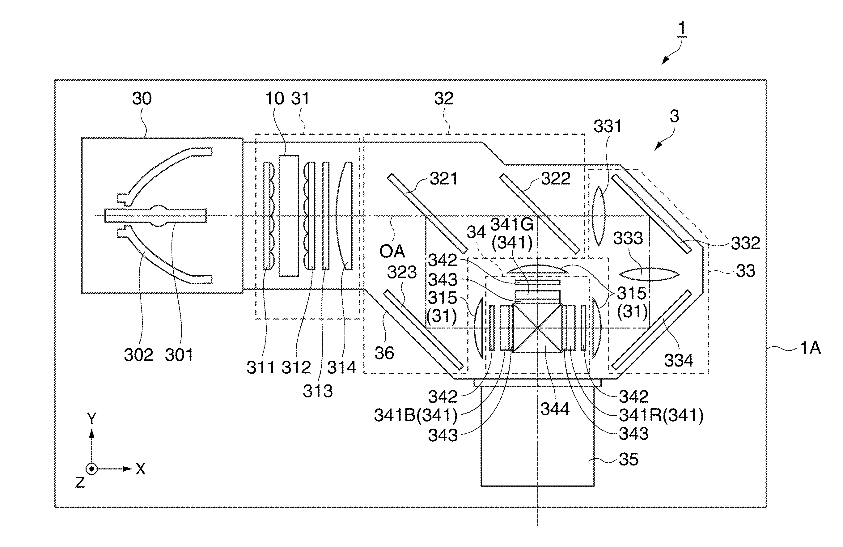
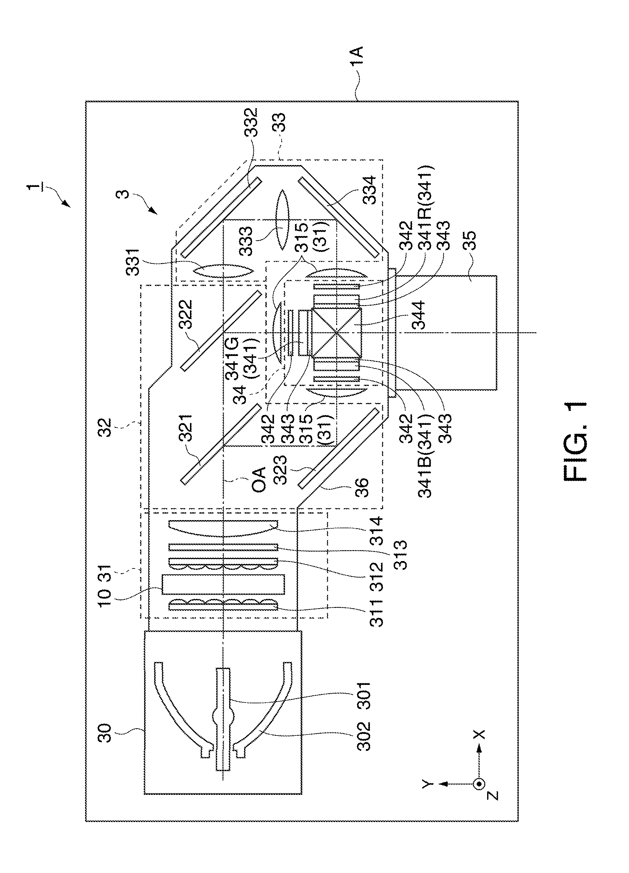
[0021]FIG. 1 is a schematic drawing illustrating a schematic configuration of a projector 1 according to an embodiment. Referring to FIG. 1, the schematic configuration of the projector 1 according to this embodiment will be described.

[0022]The drawings from FIG. 1 onward are illustrated in an XYZ orthogonal coordinate system for the convenience of description. In the XYZ orthogonal coordinate system, the direction of travel of a light flux along an optical axis OA is determined as X(+X) direction, and the direction orthogonal to the X direction opposite from the direction in which image light goes out from a projecting lens 35 is defined as Y(+Y) direction. The direction orthogonal to the X direction and the Y direction and, simultaneously, an upward direction (the direction against the direction of gravitational force) in a posture of being placed on a table is defined as Z(+Z) direction.

[0023]The projector 1 of this embodiment is electronic equipment configured to modulate a ligh...


PUM


Abstract

A light-adjusting unit includes: a light-shielding plate centered an optical axis of an incoming light flux and configured to block the light flux in response to the amount of rotation; a rotation transmitting gear configured to hold and rotate the light-shielding plate; a supporting shaft configured to rotatably support the rotation transmitting gear; and a supporting substrate on which the supporting shaft is provided, and the light-shielding plate is provided on one surface side of the supporting plate, and the rotation transmitting gear is provided on the other surface side of the supporting substrate opposite to the one surface side.

Description

BACKGROUND[0001]1. Technical Field[0002]The present invention relates to a light-adjusting unit and a projector.[0003]2. Related Art[0004]In the related art, a projector configured to modulate a light flux emitted from a light source unit by a light-modulating unit according to an image signal and project the modulated light flux on a screen or the like as image light is known. Examples of such a projector include those having a light-adjusting unit configured to adjust the light amount of the light flux to be caused to enter the light-modulating unit corresponding to the brightness of an image to be projected. The projectors having such a light-adjusting unit provide high dynamic contrast.[0005]A light-adjusting unit disclosed in JP-A-2010-175679 includes a dimming unit configured to dim a light flux emitted from a light source, a second gear and a third gear having a dimming unit mounted thereon and configured to rotate for changing the position of the diming unit, a base portion ...

Claims


Application Information

Patent Timeline
Patent Type & Authority Applications(United States)
IPC IPC(8): G03B21/20F21V21/14
CPCF21V21/14G03B21/2053
Inventor YUZAWA, FUMIO
Owner SEIKO EPSON CORP
Why Eureka
Try Eureka